The Switchboard Menu
In this page you find:
This section describes the Endian Switchboard and the functionalities it provides, including management options for the devices, the users, and their access rights.
New in version 5.0.5: The Endian Management Center.
The Connect Switchboard Architecture
The Endian Switchboard is a VPN-based solution that allows to control and manage complex infrastructures by providing a seamless connection of diverse remote devices, called endpoints, to a centralised server through gateways. Remote gateways and endpoints can be centrally managed directly from the switchboard or using the Endian ConnectApp, a desktop application that provides the same functionalities of the Switchboard. Devices can be accessed and managed by users, that are also created and managed on the switchboard, and can have different access levels to the gateways and endpoints. Endpoints can be accessed from remote workstations using application profiles.
Gateways can be added to the Switchboard literally in minutes by taking advantage of the Plug & Connect / Autoregistration procedure, that will take care of registering the gateway to Endian Network and of configuring the Green Zone and the VPN tunnel to the Switchboard. After the Plug & Connect procedure has been successfully completed, the gateway will be immediately available to the Switchboard users.
See also
A detailed description of the Plug & Connect procedure can be found in article Endian Cloud - Plug & Connect in the knowledge base.
More in detail, here follows the description of the various actors involved in the architecture.
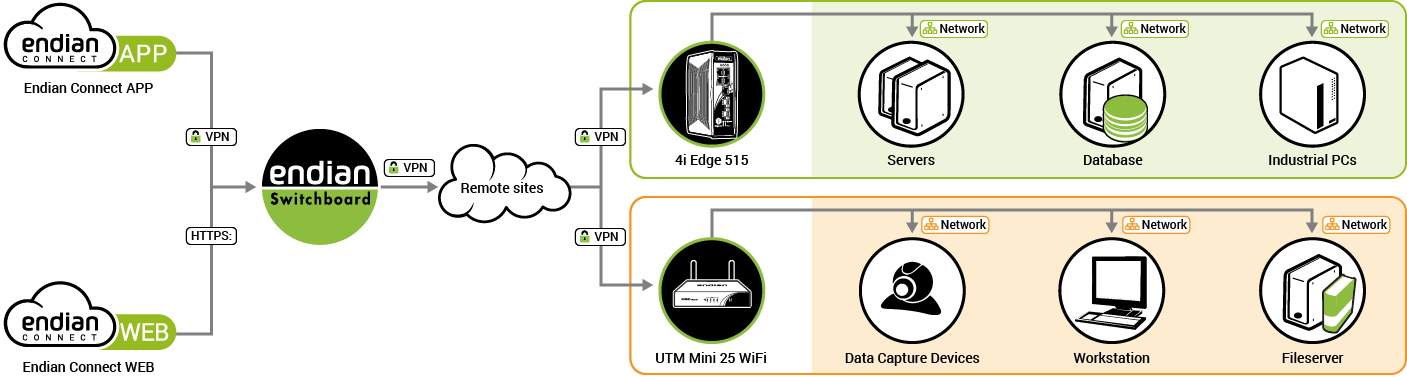
An example switchboard installation with most of the possible involved actors shown.
- Switchboard
The Switchboard is the heart of the whole infrastructure. It stores all the configuration data about gateways and users, the log files, the access policies, and keeps track of the connections. It can be accessed in two ways:
By using a browser that points to the URL https://GREENIP:10443/manage/access, in which GREENIP is the IP Address of the appliance it is installed on.
By installing the ConnectApp on a workstation that accesses remotely to the appliance on which the Switchboard is installed.
- Endpoint
An endpoint can be in principle any kind of equipment that can connect via Internet, so they can be any kind of industrial machinery, as well as remote workstation, servers and so on. Each endpoint has its own IP address and may connect to the local network and/or to the Internet by means other than the gateway. The only requirement is that the endpoint be reachable by the gateway.
Each endpoint can be connected to only one gateway and receives an unique IP address (called virtual IP in the architecture) that falls within the GREEN network of the gateway. The endpoint’s virtual IP may change when the size of the network needs to be accommodated, for example with the addition of new endpoints to the network.
- Gateway
A gateway is the door through which the Switchboard can manage and allow connections to endpoints. It can be easily configured and activated using gateway provisioning. Gateways are directly connected to the Switchboard by means of a VPN tunnel and takes care of routing connections between the Switchboard and the endpoints.
Gateways can be organised in groups and are usually in “normal” modality: they connect to the endpoints they control using their GREEN interface, and to the Internet using the RED interface. In some specific setups, gateways can be setup with an unique zone for both the uplink and the network. The GREEN subnet can be accommodated in size when the number of endpoints grows.
- Device
With device it is intended either an endpoint or a gateway.
- User
A user is anyone who can in some way access and interact with either the Switchboard, a gateway, or an endpoint. Users can be arranged in user groups, in which a user can play two roles, either be a member or an administrator of the group. In the latter case, he can manage the members of the group.
- Application profile
An application is one method to remotely access to an endpoint from a remote workstation and is defined by a path on the workstation to the program executable and by optional command argument. Since there are several possibilities to connect to an endpoint, application can be grouped together in application profiles, that encompass all possibilities to access the same type of endpoint. Each endpoint has one application profile attached, that defines all the possibilities to reach it.
- Access policy
The basic access policy on the Switchboard is that a user can have access to one or more gateways and to all the endpoints managed by these gateways.
More advanced permissions can be granted to a user, including the ability to manage users, devices, applications, organizations and use the API.
- Exclusive Access
The Endian Switchboard implements an additional access policy called Exclusive access, that can be granted at endpoint, gateway, or organization level. When this policy is enabled, only one user at a time can connect to that component, no one else can connect to it: When another user tries to access it, the switchboard prevents the connection. The rationale behind this policy is that when a user operates on a critical part of the infrastructure, like for example a gateway controlling several sensible endpoints, nobody else can interfere.
This policy is set globally: In the same Switchboard installation, there cannot be some organizations (resp. gateways, endpoints) that allow exclusive access and some that do not. Moreover, the policy is propagated downwards the hierarchy: If an organization is set to exclusive access, all the gateway have also the exclusive access set and the endpoints as well.
Finally, note that this policy can be disabled, granting concurrent access to all the infrastructure to everyone.
- Organization
When deployed in large and complex scenarios, the management of users and devices on the Switchboard can be simplified by dividing all the available resources into small, self-contained units called organizations. Organizations can be organised in hierarchies and each of them consists of users, devices, and application profiles. The root organization retains some peculiar setting, called root node characteristics, see Organizations for details, while as a general rule, sub-organization inherit access policies and application profiles, although these can be overridden.
Note
If Organizations are not enabled on the Switchboard, various options concerning them are not present in the graphic interface.
Accessing the Switchboard
Any instance of the switchboard can be accessed with different secure methods:
By accessing via HTTPS the public IP address or hostname of the Switchboard portal. This method works from any device, even from tablet and mobile phones, since the only requirements are a browser and an Internet connection and is the suggested one for administrators, since it allows access to the Switchboard settings and logs as well.
By downloading the ConnectApp, Endian's dedicated VPN client, from Endian Network (under ) and configuring a connection of type Switchboard to the Switchboard. This method works only for Windows and Mac OS X desktop platforms but as a bonus allows to use third-party applications to connect to devices located behind the Switchboard and is the suggested one for users.
After the successful login from the ConnectApp, a browser will open and connect to the Switchboard.
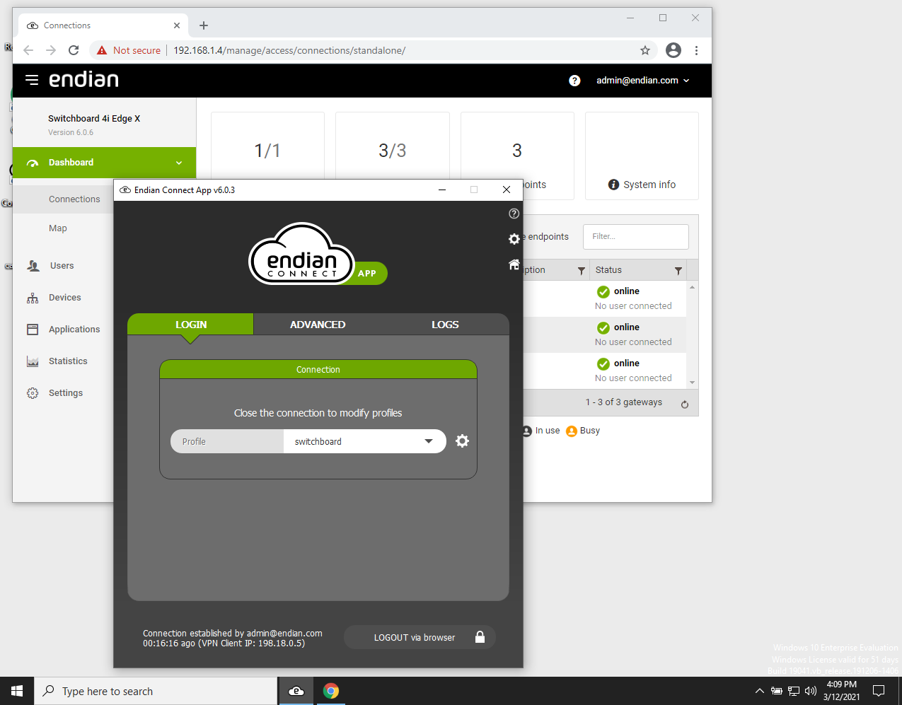
Note
ConnectApp version 6.0.1 or above is required to connect to the Switchboard version 6.0 or above, previous ConnectApp versions up to the 3.21.X will not work.
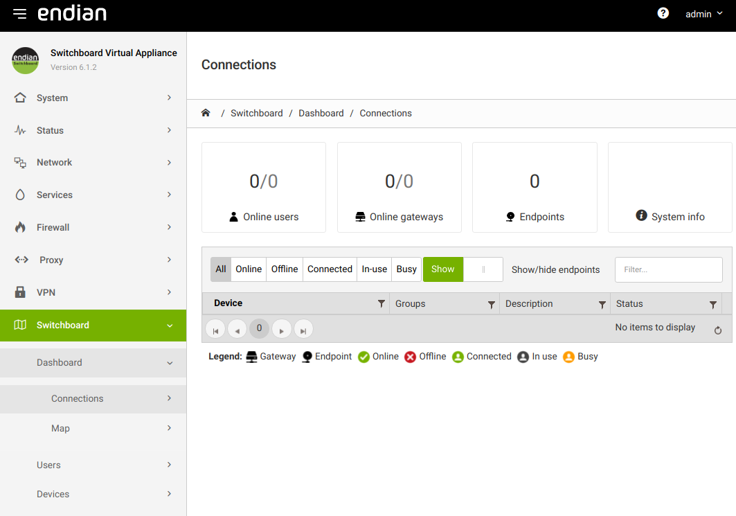
Dashboard
This page shows a number of information about the gateways and endpoints that are managed by the Switchboard and is divided into two tabs: Connections and Map. The former contains information about the connections to the devices, while the latter shows them on a world map, provided their location has been configured. Moreover, if the Message of the day under has been configured, it will appear on top of the page.
Connections
This page contains a table showing all devices configured on the Switchboard, along with the following information for each of them:
The device name, which may contain two different types of objects: Gateways
 and endpoints
  , with the latter
indented to highlight their roles and the gateway they are connected
to. The icon of a device turns grey if they are offline, and green if
someone is connected to it.
, with the latter
indented to highlight their roles and the gateway they are connected
to. The icon of a device turns grey if they are offline, and green if
someone is connected to it.Note
A small triangle on the left of a gateway denotes the presence of at least one endpoint managed by that gateway.
The organization to which the device belongs to.
The groups to which the device belongs.
A description of the device.
The device’s status, which also shows whether some user is connected to it.
Above the table, different widgets are shown.
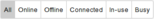
On the left-hand side, a set of buttons will allow to populate the table with only the devices that are in a given state; it is possible to show All devices, or only those that are in state Online, Offline, Connected, In-use, or Busy, simply by clicking on the button. These states are explained by the icons right above this paragraph.

In the middle, there is a switch that can be clicked to hide or show all endpoints at once, while on the right-hand side appears a filter, useful to search among all devices that are managed by the Switchboard. The matching devices will appear as soon as one character is written, concealing all those that do not correspond. The search takes place within all the fields in the table, making the filtering more effective.
When clicking on a device, either a gateway or an endpoint, an overlay appears, showing various types of information about the device.
In its upper part there is the name of the device along with its status (online or offline).
The middle section contains two tabs, Applications and Logs.
In the first one, Applications, content depends if the device is a gateway or an endpoint: for gateways, on the top right there are a few buttons:
The VPN connection to the gateway will be reset.
Establish a connections to all endpoints; any endpoint can then be reached by the current user by closing the overlay and clicking on the endpoint.
Hint
This is useful when exclusive access is enabled, to prevent another person to connect to any endpoints behind the gateway, for example because some changes must be done on the gateway that involves also the endpoints.
Establish a connection to the gateway. This action allows to use an application to connect to the gateway.
For any device, there is the list of applications that can be used to connect to the device. The small vertical bar on the left informs about the connection status to the device:
Active. There is an ongoing connection to the switchboard from the current workstation.
Busy. Someone is connecting to the device from another location.
Inactive. There is no connection to the device.
The Logs Tab contains all the actions and events that took place on the selected device. The log shown here are the same that can be found in the Switchboard's Logs section, when applying a filter containing the name of the device. More information about the data contained in the table and the actions logged can be found in the above-mentioned Logs section, which is available to the administrators on the local Switchboard instance.
At the bottom, the information displayed depends on the device: in case of a gateway, its name and the name of organization it belongs to are shown, whereas in case of an endpoint, also its real and virtual IP address and the gateway through which it is reachable are shown.
Note
To remotely connect to an endpoint, an application uses in most cases the virtual IP Address assigned by the Switchboard, although in some cases the real IP address is required.
Map
The Switchboard Map is a useful feature that shows all of the configured gateways and endpoints on a world map, based on OpenStreetMap and leaflet. In order to show the appliances on the map, they must be configured appropriately with a valid address.
The location can be set individually for each device under , after clicking on the edit icon next in the device’s Actions column and then on the Location tab. See the dedicated section for details.
When the Map tab is opened and there are devices which have not yet defined their location, an overlay box ask whether to define it now or later . A click on dismisses the overlay and opens the map, while a click on will open a list of devices for which the location is missing.
Here, for each device, write a city and possibly an address in the given textfield, then click on the search icon on the top right-hand side to confirm the location. A quick search will show the correct name as retrieved from OpenStreetMap and the device will be immediately placed on the map and shown. A click on the green check mark will save the location and show the gateway on the map. If the address is not found the search icon is replaced with a red icon.
To exit the overlay, simply click on the X on the upper right corner and you will see on the map all the devices for which the location has been set.
When opened, the world map shows all the devices whose location is known, each identified with its name and an icon, that can be clicked to show some information. Around the map, many widgets allow to carry out different actions on the map.
On the top right corner, a search bar allows to quickly find a given device. After a few characters are written, a list of possible matches is shown, from which to choose the desired one, gut if there is only one result, it will be immediately shown on the map.
On the left-hand side, a few icons allow to carry out some actions on the map:
 Zoom in the map.
 Zoom out the map.
 Open the map in full screen mode.
 Open the map in a new tab.
 Open the list of the devices’ locations, to check or modify
them.
Open the list of the devices’ locations, to check or modify
them.
Hint
It is possible to zoom the map also using the mouse wheel.
On the bottom right corner, a buttons is shown, depending if the map is in search or normal mode.
Exit from the current search and go back to the full map.
Reset the current filters.
Hint
As a shortcut for the buttons, press the ESC key.
Analytics
This page allows to access the Analytics module. Only one option is present:
A click on this button will open a new page that contains Grafana dashboards.
When accessing the Analytics module, it is possible to either change the visualisation mode, that is, to change the zooming of the dashboard, the time interval in which to show the data, and manually updating the dashboard. It is also possible to add nwew dshboard and customise them at will.
See also
The official Grafana dashboard documentation provides more detailed information and tutorials to configure new dashboards.
Users
This page is composed of two tabs, namely Users and Groups. In the former, user management can be carried out, while in the latter, users can be arranged into groups.
Users
In this page, all the users having the rights to connect to the Switchboard are listed in a table that shows the following data:
The e-mail of the user, which acts also as username.
A description of the user (e.g., the real name).
The groups the user belongs to.
The actions that can be carried out on each user.
New users can be added by clicking on the link at the top of the page, while the certificate needed by the users to connect to the Switchboard can be downloaded by clicking on the link.
In the users editor, the configuration options that can be defined are grouped into these tabs: User, Groups, Permissions, Additional user information, and Provisioning.
This tab gives access to some basic information about the user.
- Email address
The username for the new user. It must be a valid e-mail address and unique within the Switchboard or organization.
- Organization
The organization to which the user belongs to. This option is available only if at least one organization has been created.
- Description
The real name or a description of the user.
- Authenticate using external authentication server
Tick the checkbox to rely on a remote server for authentication. If selected, the two next options disappear.
Note
This option appears only if at least one remote server has been configured under .
- Password, Confirm Password
The new password for the user, to be inserted twice for confirmation. On the right-hand side of each field, a checkbox can be ticked to display the password.
- One Time Password Secret
This field shows a string that can be used as token for the 2-factor authentication by the users of the Switchboard. There are two buttons underneath:
Create a new authentication string.
By clicking on this button, a QR code is shown on the monitor, that can be acquired by the user’s smartphone and used when authenticating to the Switchboard. The button is active only when a secret has been generated.
Note
These options are only displayed if an authentication server of type One Time Password has been defined under and it has been mapped to the Switchboard service in the Authentication server mappings.
Moreover, for security and privacy reasons, these buttons are only visible to the user in his or her settings: They are never shown to the administrators or group managers.
The next two options appear only when a new user is created and are alternative one to the other: If one is enabled, the other disappears and vice versa.
- Ask for a password change at next sign-in
Tick this checkbox to force the user to change his password at the first login attempt.
- Send a link to generate the password
Tick the checkbox to send to the user an email containing a link to generate a new password.
The next two options appear only when modifying a user.
- Send an email to reset the password
By clicking on this button, a manager can send an e-mail to a user to change the password of his account. This option appears only when editing a user.
- Reset One Time Password secret
By clicking on this button, the administrator will reset the user’s OTP seed.
Passwords and OTP seed management.
Users have two possibilities to access the Switchboard, either with username and password, or by using an One Time Password, if one OTP authentication server has been configured under . Both possibilities envisage the possibility to reset the credentials (the password and the OTP seed, respectively), a task available to the managers of the group that user belongs to. The manager, however, has no access to the user’s password or OTP seed and can not change them.
When a user forgets his password, the manager can click on the Send an email to reset the password button to let the system send him an e-mail with a link to change the password. The email will be sent to the e-mail address that serves also as the username of the user’s account. The user only needs to click a link and he will be redirected to a page in which he can provide his new password.
When a user forgets his OTP seed, the manager can click on the Reset One Time Password secret button to delete the user’s OTP seed. By doing so, the user will not be allowed to log in to the Switchboard using OTP. This proves useful for example, if the device containing the OTP seed is lost or stolen, so no unwanted third party will be able to access the Switchboard. The user will receive an e-mail, which informs him to log in with username and password and generate a new OTP seed.
In this tab there is a dual-listbox widget that allows to choose the groups that the user is member of. At least one user group must have been defined to assign the user to a group.
The Roles in user groups widget is composed by two search filters, useful when a large number of groups exist on the Switchboard, on the left-hand side to search within available groups, on the right-hand side to search within selected groups. These groups appear on the bottom of the widget. In between, there is an option.
- Add as
The role that the user can assume in every group: either member of or administrator of.
Hint
To place a user in a group, chose the role then click on the available group.
Changed in version 6.1: More precise description of Switchboard permissions.
In this tab can be selected the permissions a user has on the other objects of the Switchboard. Items on the right column of the dual-listbox are the permissions granted to the user, while those in the left column can be assigned to the user, but the user can not use them yet. To move a permission from one column to the other, simply click on it, while to move all permissions from one column to the other, click on the or icons on top of the columns.
- Global Permissions
The following permissions are available.
Permission
Description
Additional Module Required
Superuser (full control)
The user can fully manage the Switchboard
This is a sum of all other permissions, except for Use the API, which is an independent permission
Manage applications
The user can manage (Create, delete, modify) the applications
The user sees the Application menu of the Switchboard
Manage organizations
The user can modify the current (root-)organization
The user can create, delete, and modify sub-organizations
The user sees the Organizations menu
Manage users
The user can manage (create, delete, modify) other users
The user sees the Users menu
Manage devices
The user can manage (create, delete, modify) devices
The usersees the Devices menu
Use the API
The user can access and use the Switchboard's RPC/REST API
Push route to GREEN zone
Routes to the Switchboard 's GREEN zone will be pushed to the user through the ConnectApp
Push route to BLUE zone
Routes to the Switchboard 's BLUE zone will be pushed to the user through the ConnectApp
Push route to ORANGE zone
Routes to the Switchboard 's ORANGE zone will be pushed to the user through the ConnectApp
Direct access to application
The user can access directly a gateway only with a given application.
See further on for a quick explanation.
Manage profile
The user can edit and modify Endian Management Center profiles
Endian Management Center
Manage analytics
The user can manage (See, browse, and define) Grafana dashboards
Analytics
View analytics
The user can see and browse Grafana dashboards
Analytics
Manage monitoring
The user can manage (see, browse, and define) monitoring alerts and profiles
Monitoring
Manage messages
The user can manage (see, browse, and define) new messages in the Message Center.
Access to sub organizations
The user can access other organizations down the hierarchy.
This permission is deprecated and should not be used!
Direct access to application
This option allows to create users that can access one gateway with a given application only. To set up this scenario, follow these three step procedure.
Create a user with permission Direct access to application.
Choose the gateway to which the user should connect.
In the Permission tab of the Device, choose the user created in step 1 as a user of the device.
Now, whenever the user connects to that gateway, the chosen application will automatically start as soon as the connection to the remote gateway is successfully established.
See also
Direct access is explained in this howto on the help portal: https://help.endian.com/hc/en-us/articles/360011541653-Configure-direct-access-permission-on-Switchboard-users
More detailed information about the user can be supplied in this tab, including the certificate to be used for the authentication.
- First Name, Last Name
The user’s first and last names
- Address, Address line 2
The address of the user, split into two lines if necessary.
- City
The city where the user is located.
- ZIP code
The city’s ZIP code.
- State or province
The state or the province where the user is located.
- Country
The country where the user is located, chosen from the drop-down menu.
- Job
The user’s job or role.
- Company
The company that employs the user.
- Certificate configuration
The drop-down menu allows to configure the user’s certificate. These are the available options.
Leave the current certificate. If the user has yet no certificate, one must be created.
Generate a new certificate
Create a new certificate directly on the Connect Switchboard, by providing the following information. The capital letters in parentheses show the field of the certificate that will be filled by the value supplied and form the Subject of the certificate.
- Subject Alternative Name
The alternative name for the subject, which allows a single certificate to be associated to multiple domains or resources. The available options are:
DNS. The DNS entry of the site.
IP. The IP address of the site.
email. An email address.
The actual value for each option must be written in the textbox on the right-hand side.
Hint
To add more alternative names, click on the button.
- Organizational unit name
The Organisation Unit (OU) to which the owner belongs to, i.e., the company, enterprise, or institution department identified with the certificate.
- Organization name
The organisation (O) to which the owner belongs to.
- Validity (days)
The number of days before the certificate expires.
- PKCS12 file password
The password for the certificate, if needed.
- PKCS12 file password Confirmation
Type once more the certificate’s password for confirmation.
- Certificate digest algorithm
Choose from the drop-down menu the algorithm to be used to generate the certificate.
Upload a certificate
In this alternative, upload an existing certificate from the local workstation to the Connect Switchboard.
- Certificate (PKCS12/PEM)
By clicking on the button or on the textfield, a file chooser will open, in which to supply the path to the certificate to be uploaded.
- PKCS12 file password
The password for the certificate, if needed. Tick the checkbox on the right-hand side to show the password’s characters.
Upload a certificate signing request
This method requires to upload a CSR from the local workstation to the Connect Switchboard, i.e., an encrypted text file containing all necessary information to generate a new certificate, recognised by the server.
- Certificate Signing Request (CSR)
By clicking on the button or on the textfield, a file chooser will open, in which to supply the path to the CSR to be uploaded.
- Validity (days)
How many days the certificate is valid.
In this tab appear two options for the management of the Endian Network credentials for the user.
- Endian Network account
The username used to access Endian Network.
- Endian Network password or registration key
The password of the Endian Network account or the Connect Switchboard's registration key.
Hint
Click on the checkbox on the right-hand side of the option to show the password.
Groups
A user group is a set of users that have access to one or more gateways or gateway groups with specific roles and permissions.
The page initially shows only the button and an empty table, that will carry the list of all the groups and some information about them:
The name assigned to the group.
A description of the group.
The available actions on each group.
When clicking on the button, the Editor opens right above the table; here, new user groups can be defined and member can be added to them.
This is the tab in which to define a new user group.
- Group name
The name given to the group. It is mandatory and must be unique.
- Organization
The organization to which the group belongs to. This option is available only if at least one organization has been created.
- Description
A description of the group.
In this tab it is possible to add users to group, by using a dual-listbox.
- User roles in this user group
Select which users belong to the group and their role: From the widget Add as choose the role, which is either member of or administrator of the group, then click on the user’s name in the left-hand side of the box to add it to the group.
Devices
This page contains two tabs, Gateways, in which to manage all devices reachable from the switchboard, and Groups, in which to configure groups of devices.
Gateways
This page contains a table with the list of all the gateways that have already been configured. Above the table, three button appear: . They are described further on.
The table displays for every device the following information:
Its name.
The organization it belongs to.
A description.
The serial number.
The groups of which the device is part.
The available actions.
Note
The configuration of a gateway is a text file that contains all the configuration options and the certificate used by the gateway.
The button allows to start the registration of a remote gateway to the Switchboard. This three-steps procedure needs a remote device connected to the Internet and a valid Activation Code for that device. By clicking on the link, a new panel appears, in which only one option is available.
- Activation Code
Supply the activation code for the remote device to be connected.
After clicking on the button, a new screen appears, showing an image of the Appliance and with a few options.
- Description
A description for the appliance. The default, self-generated value can be accepted.
- Admin Password
Enter the password for the admin user, who will access the appliance by HTTPS.
- Root Password
Enter the password for the root user, who will access the appliance by SSH or by console.
- Use the same password for admin and root user
In order to use the same password for both users, tick this checkbox.
After this step, it is necessary to connect the WAN port of the remote appliance to the Internet, for the last step of the procedure.
Hint
The remote device must be able to communicate using port 443 TCP for the procedure to complete successfully.
After a few minutes the new gateway will be shown in the list along the already registered gateways on the Switchboard. If for some reasons the procedure is not successful, error messages are shown, along with the link to the troubleshooting document.
See also
A detailed description of the plug & connect procedure, which includes the requirements to start the procedure, a more in-depth description, and troubleshooting options, can be found in article Endian Cloud - Plug & Connect.
When clicking on the gateway editor will open right above the table and a new device can be created. The editor consists of several tabbed pages, in which to configure all the different options of the gateway.
How to automatically register a gateway to Endian Network.
When the Plug & Connect (Autoregistration) procedure can not be carried out and/or it is preferred to manually add a gateway using the Add gateway method, the following requirements must be satisfied.
The credentials to access Endian Network are valid. These can be configured at global level, under , at organization level, under , or at user level, under . When more than one of these is configured, the most specific takes precedence (user over organization, organization over global).
The activation code supplied under is valid.
The System ID under is empty. IF it is not, then the system has already been registered. In this case, delete the registration first, using from the command line the command en-client -x
Warning
Beware that the command asks no confirmation and immediately deletes the registration from Endian Network.
When clicking on the link, the Switchboard‘s CA certificate will be downloaded. This certificate must be used when configuring the VPN connection on the device itself.
Add Gateway
This tab contains the basic setup options for the gateway, grouped in various tabs.
- Name
The name assigned to the new gateway, which must be unique. A default name is generated, but can be changed at will.
- Organization
The organization to which the gateway belongs to. This option is available only if at least one organization has been created.
- Description
A description for the device.
- Serial Number
The serial number of the gateway. This option is displayed only if Auto registration is not enabled.
- Use External Password Provider
Tick the checkbox to rely on a remote server for the passwords used by the gateway. If selected, the two next options disappear.
Note
The external provider must be configured under .
- Password, Confirm password
The password to access the gateway. Tick the checkbox on the right-hand side of the textbox to show in clear text the password. This option is displayed only when Auto registration is disabled or no external authentication provider has been configured.
- Enabled
Tick the checkbox to enable the device.
In this tab it is possible to choose from a dual-listbox to which groups the gateway will belong, provided some groups have already been defined in the page, see Groups of devices.
This tab contains information about all the endpoints that can be reached from the gateway and can be used to manage them.
- Local Network
The network used by the endpoints, in CIDR Notation.
- Do not translate real IPs into virtual IPs
When this checkbox is ticked, the endpoint will not be accessed via its virtual IP address, but via its real IP address.
Note
If selected, the next option is not available.
- Maximum number of endpoints
The first information to be supplied is an approximate estimate of the endpoint that will be governed by the gateway.
Note
This information is particularly relevant, as it is used to create a virtual network in which to accommodate all the IPs assigned to each endpoint. In case of doubt, choose a size larger than the actual number of endpoints, otherwise the network might not suffice to accommodate additional endpoints.
- Virtual Network
The virtual IP address to be assigned to the endpoint.
Note
When the option Enable automated virtual subnet assignment in the switchboard network settings section is enabled, this option does not appear. Indeed, an IP address for each endpoint is automatically assigned by means of the above mentioned option.
- Endpoints
A table showing all the endpoints controlled by the gateway, along with those information:
The name of the endpoint.
The endpoint’s IP address.
A description of the endpoint.
The application profile used to access the endpoint.
The Enabled status, i.e., whether the endpoint is active or not.
The Source Nat status. If active (“yes”), the endpoint will see all the traffic as originating from the gateway. This set up can prove useful when e.g., the Endpoint is situated behind a firewall and can not communicate with the outside.
A custom field.
Each field in each table’s row can be edited by double-clicking on it: Depending on the type of information it carries, each field can show a drop-down menu (i.e., a “yes-no” choice for the Enabled column, or the available profiles for the Application Profile) or a text field (all the other).
The management of the endpoints can be done using the buttons at the bottom of the table:
This option allows a new endpoint to be added to the gateway. Its configuration can be carried out by double-clicking on the fields of the new row.
By clicking on this button, the highlighted endpoint is removed from the gateway. This button is active only when one row is selected.
Warning
The deletion of a row is immediate and can not be reversed.
This button toggles the table with a textfield, containing the same information present in the table in CSV format, useful to export the configuration of all endpoints or to copy&paste the configuration.
The users or groups of users that shall have access to this gateway can be added from the dual-listbox in this tab. Each user can assume the role of either regular user or manager of the gateway.
If a group is selected, all members of that group can be selected as regular user or manager.
At the bottom of the page, above the list of devices, there is a textfield.
- Policies
In this textfield, it is possible to define custom advanced actions policies for the gateway, by using a dedicated syntax, which is described below
Warning
No validation is currently done on these rules, so please be careful!
Advanced Action Policies and their syntax.
Advanced action policies are a rather advanced technique to tweak the access to a gateway, giving managers a more fine-tuned control over the access to the endpoints managed by the gateway. In other words, advanced policies can check if user tries to access an endpoint with a given application and decide whether the access is allowed or not.
Advanced policies are composed of one or more rules with an easy syntax; writing a rule might sometimes be quicker than selecting individual permission for users on one or more endpoints, see e.g., Example 3 below.
Rule syntax
Writing a rule is straightforward:
[ALLOW|DENY] [Action1[,..,ActionN]] [ON endpoint1[,..,endpointN] [TO user1[,..,userN]] TO usergroup:usergroup1,..., usergroup:usergroupN
Each rule consists of:
A policy, either ALLOW, DENY.
A comma-separated list of one or more Actions.
Keyword ON followed by a comma-separated list of one or more endpoints.
Keyword TO followed by a comma-separated list of one or more users or one or more usergroups, prepended with the
usergroup:keyword.
All the names of actions, endpoints, and users must match existent items in the Switchboard. Moreover, if Organizations are enabled on the Switchboard, the name of an action must be qualified to include the organization as well, while the user must not include the organization’s name.
Names can be surrounded with quotes or double quotes. To match any item, the wildcard * can be used, or it is possible to omit it entirely, see examples below. The keyword gateway can be used in policies involving the gateway itself.
Evaluation of rules
Whenever a user tries to connect to an endpoint, rules are evaluated from top to bottom. As soon as a matching rule is found, the policy is applied and the evaluation is terminated.
It is also suggested to always include DENY as the last policy.
Examples
Example 1, basic policies.
1ALLOW 'Secure Shell','Web Admin' ON endpoint1 TO sww@example.org
2ALLOW 'Web Admin' TO fls@example.org
3DENY
This policy allows user sww@example.org to access to endpoint1 with applications Secure Shell and Web Admin. It also allows user fls@example.org to use Web Admin on all endpoints. No other user is allowed to access in any way to any endpoints managed by the gateway.
Example 2, wildcards.
1DENY
2DENY * ON * TO *
3DENY * TO
4DENY * ON
These are all equivalent policies to deny all users to access all endpoints.
Example 3, multiple policies for a single user.
1ALLOW 'Secure Shell' ON endpoint1 TO sww@example.org
2ALLOW 'Web Admin' ON endpoint2 TO sww@example.org
3DENY 'Secure Shell' ON gateway TO sww@example.org
4DENY
This example shows how user sww@example.org can access endpoint1 using SSH, endpoint2 using a browser. The user can not access the gateway using SSH, but is (implicitly) allowed to access it by other means. He can not access any other endpoint.
Example 4, Organizations and wildcards.
1ALLOW 'Secure Shell/ACME' ON endpoint1 TO sww@example.org
2ALLOW 'VNC Remote Desktop/ACME' TO fls@example.org
3ALLOW * ON endpoint1 TO fdd@example.org
4DENY * ON gateway TO rpt@example.org
5ALLOW * ON * TO rpt@example.org
6DENY
This example involves organizations; these policies…
Allow sww@example.org to access, within organization ACME to access endpoint1 using SSH.
Allow fls@example.org to access, within organization ACME to access all endpoints using VNC.
Allow fdd@example.org to access endpoint1 with any application, independently of the organization.
Forbid rpt@example.org to access the gateway, with any means, but allow her to access all endpoints with any application.
In this section it is possible to define the configuration for a remote gateway. It is then possible to download the configuration, copy it on a USB stick and used to automatically configure the gateway when delivered on-site and installed.
See also
The Provisioning procedure is described in a dedicated article on Endian's help portal.
The available configurations options are:
- Model
Choose the model of the device from those available in the drop-down menu.
- Activation code
The activation code used to set up the gateway.
Immediately after the choice of the model, all the configuration options for it will be displayed and can be configured.
Note
Depending on the type of the model chosen, some of the options available will be prefilled with suitable values.
General settings
- Root password
Choose the password for the root user, used for SSH (console) access.
- Admin password
Choose the password for the admin user, used for HTTPS (browser) access.
- Host name
The hostname of the gateway
- Domain name
The gateway’s domain name.
- Company
The company to which the gateway belongs
The reference e-mail for the gateway, usually of the responsible person for that gateway.
- Timezone
The timezone in which the gateway is located.
- Country
The country where the gateway is located.
Uplink
- Red type
The type of the RED interface, i.e., how the gateway connects to the Internet. The following options are available: DHCP, Static, No uplink, 3G/4G, UMTS, and Wi-Fi.
Note
The UMTS uplink type is available only to provision 5.0 and 5.1 Endian appliances, while on 6.0 it is included in 3G/4G option.
- Red device
The interface that connects the gateway to the Internet. The available options in this drop-down menu are determined by the Model chosen above. This option does not appear when the Red type is set as No uplink
The following options are displayed according to the selected type of red device. By choosing DHCP, none of them will appear.
Hint
For a full desription of all options, please refer to section Uplinks under .
- Red IPs/CIDRs
The IP address of the RED interface. This option appears only when the RED type is Static.
- Red gateway IP
The IP address of the gateway for the RED interface. This option and the next one is needed to access the Internet and appears only when the RED type is Static or No uplink.
- DNS Servers
The IP addresses of the DNS server used by the gateway, one per line. It appears only when the RED type is Static or No uplink.
- Access Point Name
The name of the access point, appears only in the 3G/4G and UMTS Red Type.
- Modem Type
This option appears only for the 3G/4G Red Type and allows to select the type of modem to be used from the drop-down menu, among those available: 3G/4G or CDMA
Zones
- Green device
The interface of the GREEN zone, i.e., the one in which the endpoints are situated.
- Green IPs/CIDRs
The IP address pool assigned to the GREEN zone.
- Blue device
The interface of the BLUE zone.
- Blue IPs/CIDRs
The IP address pool assigned to the BLUE zone.
- Orange device
The interface of the ORANGE zone.
- Orange IPs/CIDRs
The IP address pool assigned to the ORANGE zone.
OpenVPN
- Custom OpenVPN server IP/FQDN, port, and protocol
A custom address used by the endpoint to connect to the OpenVPN server.
Hint
The format to be used for the address in this and in the next option is hostname.domain:port:protocol or IP.address:port:protocol, with the port or protocol as optional, hence valid values include vpn.example.com:1197:udp and 123.45.67.89:1192.
If the protocol is specified, the port must be specified as well.
- Custom OpenVPN fallback IP address/FQDN, port, and protocol
A custom address used by the endpoint to connect to the fallback OpenVPN server.
- OpenVPN through HTTP proxy
Tick the checkbox when the gateway uses a proxy for its connection to the Internet. The next four options will appear to configure that proxy.
- Upstream server
The IP address of the upstream proxy server.
- Upstream port
The port on which the proxy service runs on the server.
- Upstream user
The username to connect to the proxy server, if needed.
- Upstream password
The password to connect to the proxy server, if needed.
- Upstream NTLM proxy authentication
Click the checkbox if the upstream HTTP proxy requires NTLM Authentication.
- Forge proxy user-agent
If the upstream HTTP proxy needs to be contacted with a given user-agent, write it here.
Plug & Connect
- Plug & Connect public IP/FQDN
Insert the IP address or FQDN that should be used by clients to access this Connect Switchboard and be registered using the Plug&Connect procedure.
- Plug & Connect clients
Select the clients that are available for the Plug & Connect procedure
Advanced options
In this panel there is an additional option:
- System ID
Provide an explicit System ID to the device.
The options in this tab can be used to define on the gateway suitable port-forwarding rules that allow to redirect traffic coming from an endpoint to a given host. The port forwarding rules are pushed on the Gateway via the OpenVPN connection.
The table contains the following information for each endpoint.
Endpoint. The endpoint for which the rule is defined. No choice is available if no endpoint has already been set up.
Incoming IP. The gateway’s public IP address on which to apply the rule.
Incoming ports/ranges. The port or range of ports on which to apply the rule.
Protocol. The protocol that shall be used in the rule: Available choices are tcp, udp, tcp+udp, or icmp.
Remote IP. The remote IP address to which the traffic is forwarded.
Remote port/range. The port on the remote IP to which the traffic is forwarded.
Description. A custom remark about the gateway.
Each field in each table’s row can be edited by double-clicking on it: Depending on the type of information it carries, each field can show a drop-down menu (i.e., the list of the endpoint for the Endpoint column, or the available protocols for the Protocol columns), or a text field (all the other).
The management of the rules associated with the endpoints can be done using the buttons at the bottom of the table:
This option allows to add a new rule. Its configuration can be carried out by double-clicking on the fields of the new row.
By clicking on this button, the highlighted rule is deleted from the set. This button is deactivated if no row is selected.
Warning
The deletion of a row is immediate and can not be reversed.
This button toggles the table with a textfield, containing the same information present in the table in CSV format: This proves useful to export the whole set of rules.
In this tab it is possible to assign a location to the device using either the Location Editor Map or the two small text fields below.
In the map, use the and buttons to resize the
maps to your needs or use directly the text field.
- Search…
In this textfield, write an address and optionally also the city and country. If a match is found, an icon is positioned on the map, if more result are available, choose the most appropriate one.
Note
When an address is selected, the two textfields below are automatically filled in.
It is also possible, instead of supplying the address, to give the coordinates of the device location:
- Latitude
Enter in decimal form the latitude where the device is installed
- Longitude
Enter in decimal form the longitude where the device is installed.
If the device is moved from its current location into a nearby one, it is possible to drag the icon to the new location: the new address and coordinates will be updated automatically.
Groups
The page contains only the link above a table (initially empty) carrying the list of all the existent groups and some information about them:
The name assigned to the group.
A description of the group.
The available actions.
When clicking on the link, the editor opens right above the table. The setup options are grouped in three tabs: Group, Members, and Permissions.
Add Device Group
This tab contains basic information about the group.
- Group name
The name assigned to the group.
Note
This name must be unique within gateway groups and is the first option to be defined.
- Organization
The organization to which the group belongs to. This option is available only if at least one organization has been created.
- Description
A description of the group.
This tab contains information about the members of the group. Two options are available:
- IP pool
The IP pool from which all devices in the group obtain an IP address.
Hint
Use CIDR notation for the pool.
- Devices in this gateway group
Choose which gateway are part of this group.
- User permissions on this device group
Select all users that can access this group and the role (i.e., either regular user or manager) they can assume.
Applications
There are two tabs in this page: Applications, in which to define all possible means to connect to an endpoint, and Profiles, in which to group together several applications and assign them to a device.
Applications
An application can be seen as a means to access from a remote PC or workstation equipped with the Endian S.r.l., Italy ConnectApp to an endpoint or to a service running on an endpoint, possibly using a third-party software installed on the workstation.
The page initially shows the link and a table containing the applications available by default and other information:
The name given to identify the application.
The type of the application (see further on for more information).
Some details about the protocol and port(s) used by the application.
A description of the application
The available actions for each application.
Above the table, on the right-hand side appears a filter, useful to search among all applications that have been defined in the Switchboard.
When clicking on the link, the applications editor opens right above the table, giving the opportunity to define additional applications.
Add Applications
Two tabs are present in this editor: Application and Advanced parameters. The latter appears only for some of the Application types available.
- Name
A name to identify the application.
- Organization
The name of an organization to which the use of the appliance is reserved. At least an organization must have been defined in the Organizations section for this option to appear.
- Description
A description of the application.
- Application type
The type of the application, which can be selected from the drop-down menu.
Note
The choice of the application type influences also the availability of some of the next options; also the options that appear in the Advanced Parameter tab will depend on the application type chosen.
- Protocol
The protocol that the application should use, chosen from the drop-down menu. It can be TCP, UDP, or TCP & UDP.
- Port
The port used by the application.
- URL to open
The URL to be used for the connection. This option is available only when the Application type above is either HTTP or HTTPS.
- External URL
Tick the checkbox if the URL to open is different from the remote device.
Opening External URLs
The URL to Open option allows to select a URL that the application will open, which always points to the %DEVICE_IP% IP Address, which is the IP address assigned to a remote device (See Available placeholders below). When also the External URL option is enabled, it is possible to open a different URL, that might not be related to the remote device, and can include also placeholders.
Some example, assuming that the remote device has IP address (%DEVICE_IP%) 10.64.100.12, when the External URL option has been enabled.
https://%DEVICE_IP%:3000/   https://10.64.100.12:3000/

https://host.local:1800/  https://host.local:1880/

https://host.local:1800/target=%DEVICE_IP%  https://host.local:1880/target=10.64.100.12
- Enabled
Tick the checkbox to enable the application.
Connect App for Windows
Note
Depending on the Application type chosen, the following option may appear or not.
The next options appear only if the Application type above is Custom and allow to define both the path on the local Windows workstation (the one from which the connection to the Switchboard was started) to launch the application and the arguments to be passed to the program. It is possible to use placeholders, that will be replaced accordingly, see below for more details.
- Command path
The full path to the program to use.
- Command arguments
Additional arguments to be passed to the program.
The next options concern how the ConnectAPP launches the application to connect to the remote device.
- Enable integrated application
By selecting this option, the ConnectAPP will use its integrated application for the remote connection.
- Open external application
By ticking this checkbox, it will be possible to specify which external application will be launched to establish the connection to the remote device. Two more option will appear, Command path and Command arguments, that are exactly the same described above and for which it is possible to use the placeholders described next.
Connect App for Mac OS X
Note
Depending on the Application type chosen, the following option may appear or not.
The next options appear only if the Application type above is Custom and allow to define both the path on the local Windows workstation (the one from which the connection to the Switchboard was started) to launch the application and the arguments to be passed to the program. It is possible to use placeholders, that will be replaced accordingly, see below for more details.
- Command path
The full path to the program to use.
- Command arguments
Additional arguments to be passed to the program.
The next options concern how the ConnectAPP launches the application to connect to the remote device.
- Enable integrated application
By selecting this option, the ConnectAPP will use its integrated application for the remote connection.
- Open external application
By ticking this checkbox, it will be possible to specify which external application will be launched to establish the connection to the remote device. Two more option will appear, Command path and Command arguments, that are exactly the same described above and for which it is possible to use the placeholders described next.
Available placeholders.
The purpose of a placeholder is to allow the same application to be used on every device, independently of the varying configuration values of each device, like for example their (public) IP addresses.
Placeholders can be used in the HTTP, HTTPS, and Custom application types.
For HTTP and HTTPS types, these are the available placeholders:
%DEVICE_IP% the IP address assigned to the device.
%PHYSICAL_IP% the physical IP of the device.
%SERVER_EXTERNAL_HOST% the FQDN of the server’s public hostname.
%SERVER_INTERNAL_IP% for the internal, private IP address.
In the Custom application type, the available placeholders are:
%PROGRAM_PATH%: The default installation directory for applications (usually C:\Program Files).
%SYSTEM_DRIVE%: The drive containing the Windows root directory (C:\).
%SYSTEM_ROOT%: The Windows root directory (C:\Windows).
%HOME_PATH%: The user’s home directory (C:\Documents and Settings\`username`).
As an example of application, suppose that each workstation equipped with Windows and the ConnectApp has also the program PuTTy installed in user’s home directory. To allow users to use putty to connect via SSH, define an application with the following configuration values:
Name: PuTTy -SSH
Description SSH via PuTTy
Application Type: Custom
Protocol: TCP
Port: 22
Command path: %HOME_PATH%\putty.exe
Command args: username@%DEVICE_IP%
Note that username must be a valid user account on the endpoint.
Depending on the application type chosen in the other tab, the following common options are available for all types except for Custom.
See also
To find more detailed information about the configuration of the advanced options of the VNC, RDP, SSH, and Telnet connections, refer also to the Connection configuration section in the guacamole manual.
Advanced protocol configuration
- Username
The username used for the remote login.
- Password, Confirm Password
The password that is used for the login, repeated twice for confirmation.
There is also the possibility to define advanced options for the following types:
SSH
- Private key
Use the textfield to paste the private key used for the connection.
- Passphrase, Confirm Passphrase
Write here the passphrase that corresponds to the private key.
- Terminal color scheme
Select from the drop-down menu the colors used in the SSH terminal.
- Font
The font used in the terminal.
- Font size
The size of the font.
RDP
There are a number of options that can be configured with this type of connection, but they are not required in most cases. These options allow to customise the authentication, the session, the audio support, some performance boost, and the RemoteApp.
VNC
- Number of connection retries
The number of times the connection should be attempted after an unsuccessful try.
- Color depth
Choose the color depth used for the connection.
- Swap red-blue
Invert the red and blue colours.
- Cursor
Choose from the drop-down menu whether to use the local or remote cursor.
- Read only connection
Tick the checkbox to disallow the client to make changes on the remote device.
- Clipboard encoding
The encoding to assume for the VNC clipboard. This should be changed only if the VNC server supports encodings different from the standard ISO 8859-1.
Telnet
- Username regex
The regular expression that recognises the correct moment when to send the username to the remote device.
- Password regex
The regular expression that recognises the moment when to send the password to the remote device.
- Terminal color scheme
Select from the drop-down menu the colors used in the SSH terminal.
- Font
The font used in the terminal.
- Font size
The size of the font.
Custom
For custom applications, click on to add a new parameter, and then fill in the following information:
- Parameter name
The name of the parameter.
- Value
The value of that parameter.
It is possible to add any number of options and their values, these will be passed on the command line to the application.
Profiles
Applications can be grouped together into Profiles and attached to single endpoints, tailoring the possibility to access them. In other words, it is possible to configure applications on a given endpoint so that it can be reached only via some given protocols (e.g., RDP, SSH or HTTP) or services (e.g., VNC). The choice of the applications can be influenced also by the endpoint’s running operating system and services.
The page contains the button, above the table carrying the list of all the available profiles and some information about each profile:
The name given to the profile.
The applications that are part of the profile.
The available actions on each profile.
Note
In case one or more profiles are deleted, the single applications will not be deleted: To remove an existing application, go to Applications.
Above the table, on the right-hand side appears a filter, useful to search among all profiles that have been defined in the Switchboard.
When clicking on the link, the editor opens right above the table. Here, additional profiles can be created, by supplying the following information:
Add Profile
- Name
A name to identify the profile.
- Organization
Select for which organization the Profile will be available.
- Description
A note about the profile.
- Applications
Available applications are listed in this dual-listbox. To search for an application, use the textbox on top of the box, To move an application from one column to the other, simply click on it, while to move all applications from one column to the other, click on the or icons on top of the columns.
Organizations
An important feature of the Switchboard are Organizations that have been introduced to add support for a more granular division of complex enterprises into smaller, self-contained units–called indeed organizations.
Note
Organizations are not enabled by default on the Switchboard; they are a feature that must be requested when purchasing a Switchboard licence.
A Switchboard organization consists of one or more users and of one or more devices, be it gateways or endpoints. Users and devices within one organization can not see, access, or manage users and devices in other organizations. A user, a user group, or a device can belong to exactly one organization.
Within an organization, the default policy is that users can see all other users and all the devices they created or to which they have been granted permission.
From a technical viewpoint, each organization is a sub-organization of a root node, which has some default properties that all organizations inherit and cannot modify. These root node characteristics are:
OpenVPN: dedicated servers or instances, possibly with a fallback, and public IP address of FQDN.
A dedicated IP address pool, with manual or automatic virtual subnet assignment.
The possibility to push the entire virtual IP pool to the clients connected.
A unique Switchboard bind IP address, possibly with fallback.
This page initially contains an empty table of the available organizations, and some information about each of them:
The organization’s name.
The path (from the root organization)
The available actions on each organization.
A link above the table, , allows to define a new organization.
In the editor, the options available to create a new organization are grouped into four tabs, namely Organization, Network, Portal, and Provisioning.
Organizations
- Unique Organization Identifier
An identifier used for the identification of the organization, which must be unique within the instance of the Switchboard. This identifier is mandatory for the new organization.
- Parent organization
If this is not the root organization, select from the drop down menu its parent.
- Exclusive access
Select from the drop-down menu whether to enable exclusive access (at either Endpoint of Gateway level) to the whole organization or to disable it.
- Max number of nodes
Define the highest number of nodes that will be allowed within the organization.
- Add default applications and profiles
If ticked, the default application and profiles will be available within the new organization.
Organization information
- Organization Name
The name of the organization.
- VAT number
The VAT number of the organization.
- Address, Address line 2
The address of the organization.
- City
The city in which the organization is located.
- ZIP code
The city’s ZIP code.
- State or province
The state or province in which the organization is located.
- Country
The country in which the organization is located.
The e-mail of the organization.
- Website
The website of the organization.
- Phone number
The phone number of the organization.
- Fax number
The Fax number of the organization.
API
- Enable remote API
Tick the checkbox to enable the remote API.
- API key
A string used as the key for accessing and using the API.
Network
- Switchboard bind IP address
It is the IP address on which the Switchboard listens for connections. It is mandatory when more IP addresses are assigned to the Switchboard.
OpenVPN
- OpenVPN Instance
This option only appears if on the Connect Switchboard multiple instances of the OpenVPN server are running. Choose the instance to be used for the Switchboard from the drop-down menu.
- OpenVPN server public IP/FQDN and port
The public IP address or FQDN to be assigned to the Switchboard.
- Enable fallback OpenVPN instance
Tick the checkbox to allow a fall back instance of the OpenVPN server, in case the main one can not be reached. The next two options will appear.
- Fallback OpenVPN instance
The fallback OpenVPN instance used in case the one specified in the previous option does not run, chosen from the drop-down menu.
- Fallback OpenVPN server public IP/FQDN and port
The public IP address or FQDN to be assigned to the fallback server of the Switchboard.
Virtual Subnet
- Enable automated virtual subnet assignment
Tick this checkbox to allow the virtual IP addresses for the subnets to be automatically assigned. When enabled, the next option appears.
- Global virtual IP pool
This options defines the IP address subnet for the addresses of the gateways.
- Push entire virtual IP pool on client connection
With this option enabled, whenever a client connects, the whole virtual IP subnet will be pushed to it.
Portal
In this tab it is possible to modify a few options that influence the appearance of the portal.
- Portal fully qualified domain name
Write in the textfield the FQDN to which users can connect to access the Organization’s portal.
- Portal logo
Click on the button to select the logo for the portal to be uploaded.
- Logo URL
Write in the textfield the URL where the logo is located.
- Login logo
Click on the button to upload the logo to be shown at the login.
- Login Logo URL
Write in the textfield the URL where the login logo is located.
- Stylesheet
Click on the button to select a CSS stylesheet that will be used for rendering the portal.
- Stylesheet URL
Write in the textfield the URL of the CSS stylesheet.
- Icon
Click on the button to select an icon to be uploaded.
Hint
Unlike the other logos, the icon must be in wither ico or gif format.
- Icon URL
Write in the textfield the URL where to find the portal’s icon.
- Welcome message
The message displayed to the users that connect to the portal.
- Enable mandatory confirmation of notification messages
Tick this checkbox to enable the receipt on notification messages.
Notifications
- Enable mandatory confirmation of notification messages
When the checkbox is ticked, any notification shown in the portal requires to be confirmed, i.e., by clicking on it.
Provisioning
- Enable gateways provisioning
When this checkbox is ticked, gateway provisioning is enabled. See below for more information. The following two options appear.
- Endian Network account
The username for accessing Endian Network, used for the automatic registration of the gateways.
- Endian Network password or registration key
The registration key of the endpoint. Tick the checkbox on the right-hand side to show the password, which is otherwise hidden.
- New gateways default model
Choose from the drop-down which should be the default model of new-added gateways.
Outgoing Mail
This section allows to configure a smarthost to send system e-mails. Unlike the settings in Outgoing Mail, the smarthost is configured only for the current organization. The following options are available.
- Use global settings
Tick the checkbox to use for this organization the global defined smarthost.
Note
If a dedicated smarthost is used for an organization, untick this option to show the additional configuration options. The are the same as in section Outgoing Mail: Refer to that section for any help.
- Email stylesheet
Click on the button to upload a CSS stylesheet that will be applied to all outgoing e-mails.
- Email stylesheet (CSS) URL
Write in the textfield the URL of a CSS stylesheet that will be applied to all outgoing e-mails
Statistics
This page is divided into three parts, presenting statistics about the Organizations, the Users, and the Devices respectively, that exist on the Switchboard. Each tab contains a table, with a filter bar above it, that allow to search within the elements in the table:
Filter: a research string.
Organization: select from the drop-down menu the Organization in which to search.
From, To: select the time interval in which to look up. To select a given day, select it in both the From and To fields.
Organizations
This page shows a table containing the list of currently defined organizations, with a number of information. This tab does not appear if Organizations are not enabled on the Switchboard.
Note
The numbers in parenthesis are the values of the child organizations.
Organization. The name of the organization, along with its ID and its path from the root organization.
Users. The number of users that belong to the organization.
Devices. The number of devices, which are grouped in three categories: Gateways, Endpoints, and Endian Appliances.
Nodes. Two values associated with the nodes: Counted nodes - the number of nodes the organization has, and Node limit - The maximum number of nodes allowed.
Traffic. The amount of traffic Sent from or Received by the organization.
Users
This page shows a table containing the list of the users that have connected through the Switchboard.
User. The account name and the organization it belongs to.
Organization. The name of the organization, along with its ID and its path from the root organization.
Note
This column appears only if Organizations are enabled on the Switchboard.
Connections. To Switchboard is the number of connections to the switchboard made by the user, while To devices the number of connections to devices.
Connections Time. To Switchboard is the amount of time spent by the user on the switchboard, while To devices the time spent on the devices.
Traffic. The amount of traffic that has been made by the user, divided into Sent by the user and Received from the user.
Devices
This page shows a table containing the list of devices connected to the Switchboard and a number of information about them.
Device. The name of the device and the organization it belongs to.
Organization. The name of the organization, along with its ID and its path from the root organization.
Note
This column appears only if Organizations are enabled on the Switchboard.
Connections. To Switchboard is the number of connections to the switchboard made by the device, By users shows how many users have connected to the device.
Connections Time. To Switchboard is the amount of time during which the device has been connected to the switchboard, while By users is the amount of time during which the users were connected to the device.
Traffic. The amount of traffic that has been made by device, divided into Sent by the device and Received from the device.
Client Download
From here it is possible to download the ConnectApp, that can be installed on a local workstation and used for both the management of the Switchboard and for launching a direct connection to the remote devices, using the application profiles defined on the Switchboard and provided that the necessary applications are installed on the workstation.
Settings
Note
This section appears only in the Switchboard on premises, not in cloud instances.
This page allows to set up all the global configuration options of the Switchboard. Before actually configuring the Switchboard, it is mandatory to accomplish two tasks in two other modules: Firewall and VPN
Preliminary set up tasks
The first task consists in the activation of the VPN Firewall, as this is required by one option in the OpenVPN server. To complete the task, go to and, if not yet active, click on the grey switch .
Once that the VPN firewall has been enabled, the second task requires to set up a couple of options in the VPN module.
Indeed, the Switchboard relies on an OpenVPN instance running on the Connect Switchboard to provide secure connections between the clients and the devices. While most of the OpenVPN instance’s parameters can be freely chosen, two of them must be configured as follows:
The traffic on the OpenVPN’s device must be routed.
The traffic between the clients must be filtered.
The configuration options interested are:
In the Network options, the Bridged checkbox must not be ticked. Hence, if TAP is selected, do not tick the checkbox.
Note
When the TUN device is chosen, the traffic can only be routed and the checkbox is not accessible.
Under Advanced Options, the option Client to client connection should be set to Filter connection in the VPN firewall.
More information about the aforementioned options can be found under .
This page contains four tabs, which group all configuration options for the Switchboard: Settings, Network, Portal, Provisioning, and Outgoing Mail.
General Settings
- Fully qualified domain name
This option sets the FQDN through which the Switchboard is reachable.
- HTTPS certificate
Choose from the drop-down menu which certificate shall be used for this Switchboard instance
Hint
A new certificate can be created under .
- Enable Management Center
Tick the Checkbox to enable the Management center. See Section Management Center for details.
Connections
- Exclusive access
This options governs the ability to lock single endpoints within a gateway, or even a whole gateway, allowing exclusive access to one user at a time. Three options are available, disabled–no exclusive access is granted, on gateway level–a whole gateway including its endpoints can be locked, and on endpoint level–single endpoints can be locked.
- Enable VPN connection check (ping)
When the checkbox is ticked, an ICMP ping packet will be periodically sent through the VPN tunnel to ensure the connection is still alive.
When enabled, the next two options appear.
- VPN connection check timeout (in seconds)
The interval between two successive checks.
- VPN connection check attempts
How many times a failed check will be re-issued before the VPN connection is considered dead.
Password Management
- Allow sending email for generating and resetting passwords
By ticking the checkbox, it will be possible to send an email to user to either reset the password–for existing users, or to generate the password–for new users. Suitable options appear in the Switchboards user editor under .
API
- Enable remote API
Tick the checkbox to enable the remote API.
- API key
A string used as the key for accessing and using the API.
Network
- Switchboard bind IP address
It is the IP address on which the Switchboard listens for connections. It is mandatory when more IP addresses are assigned to the Switchboard.
OpenVPN
- OpenVPN Instance
This option only appears if on the Connect Switchboard multiple instances of the OpenVPN server are running. Choose the instance to be used for the Switchboard from the drop-down menu.
- OpenVPN server public IP/FQDN and port
The public IP address or FQDN to be assigned to the Switchboard.
Hint
The FQDN must be typed in all lowercase.
- Enable fallback OpenVPN instance
Tick the checkbox to allow a fall back instance of the OpenVPN server, in case the main one can not be reached. The next two options will appear.
- Fallback OpenVPN instance
The fallback OpenVPN instance used in case the one specified in the previous option does not run, chosen from the drop-down menu.
- Fallback OpenVPN server public IP/FQDN and port
The public IP address or FQDN to be assigned to the fallback server of the Switchboard.
Hint
The FQDN must be typed in all lowercase.
- Gateways must accept weak OpenVPN server certificates
Tick the checkbox to enable OpenVPN to support certificates generated using weak encryption algorithms which are no longer supported by default.
Warning
Enabling this feature will weaken the security of the Connect Switchboard and is not recommended.
Hint
This feature is usually only used for backwards compatibility with older gateways (which cannot be upgraded).
Virtual Subnet
- Enable automated virtual subnet assignment
Tick this checkbox to allow the virtual IP addresses for the subnets to be automatically assigned. If disabled, these options appear:
- Manually define IP pool for each gateway group
When ticked, this option allows to define a different IP Address Pool for each Gateway Group.
- Global virtual IP pool
This options defines the IP address subnet for the addresses of the gateways.
- Gateway maximum virtual network netmask
The netmask for the Switchboard's network. It determines the size of the network and therefore the number of endpoint that can be managed by the gateways.
- Push entire virtual IP pool on client connection
With this option enabled, whenever a client connects, the whole virtual IP subnet will be pushed to it.
Portal
This page allows to configure the portal and contains initially only two options.
- Enable Portal
Tick the checkbox to enable the portal, used by the ConnectApp (see Section Accessing the Switchboard). The next option will appear.
- Welcome message
A message shown to those users who connect using the ConnectApp, which defaults to
Welcome to the Switchboard, access
to the system is monitored
Changed in version 6.1.0: Default message changed to comply with IEC 62443 certification.
Notifications
- Enable mandatory confirmation of notification messages
Tick this checkbox to enable the receipt on notification messages.
- Message of the day
A message shown to all users connecting to the Switchboardusing a standalone connection..
session settings
New in version 6.1.0: Soft lockout option
- Session lock timeout
This option controls the inactivity period of the user, i.e., the amount of time after which the session expires and an inactive user is logged out.
See also
The difference between soft and hard lockout.
Provisioning
In this page it is possible to specify the options for the gateway provisioning. Initially it contains only an option and a list of models.
- Enable gateways provisioning
Tick the checkbox to enable provisioning. The next options will appear.
- Send provisioning to the registry
Tick the checkbox to send the configuration of the provisioning to Endian's repository of configuration. Endpoints will be able to download these configurations file and self-configure themselves
- Provisioning digest algorithm
Use the dropdown box to select the hashing algorithm you wish to use for encrypting the provisioning file. The default and most secure is sha256. The alternative md5 is considered less secure but provides compatibility for legacy devices.
- Endian Network account
The username used to access Endian Network
- Endian Network password or registration key
The password of the Endian Network account or the Connect Switchboard's registration key.
- Provisioning Encryption Certificate (PEM)
Copy and paste here the content of the .pem certificate file selected for the provisioning.
- Provisioning Encryption Private Key (PEM)
Copy and paste here the content of the .pem file containing the private key corresponding to the selected certificate..
- New gateways default model
Choose from the drop-down which should be the default model of new-added gateways.
At the bottom of the page, it is possible to add new models of Endian appliances that can be used in the provisioning. The table consists of those fields:
- Name
The name given to the gateway.
- Interfaces devices
The name of the network interfaces available in the appliance. The Default models panel below the table can be used to copy and paste the correct network interfaces.
- OpenVPN >= 2.3
Choose from the drop-down menu whether the appliance is equipped with at least version 2.3 of OpenVPN.
- Modem port
Choose from the drop-down menu which port should be used as modem port.
The management of the gateways can be done using the buttons at the bottom of the table:
This option allows a new gateway to be added to the list. Its configuration can be carried out by double-clicking on the fields of the new row.
By clicking on this button, the highlighted gateway is eliminated from the list. This button is active only when one row is selected.
Warning
The deletion of a row is immediate and can not be reversed.
Default models
In this table appear the various Endian appliances that can be configured through provisioning and their default values to be used in the table above.
Outgoing Mail
In this page it is possible to configure a smarthost that will take charge the duties to send all the e-mails that the Switchboard needs to send for its correct working, like e.g., the user’s credentials or a link to reset the password. Only one option is present by default.
- Use global settings
The default smarthost configuration defined on the Connect Switchboard will be used. If not enabled, the following options are available.
- Email sender address
The e-mail address that will appear as the sender of the Switchboard’s e-mails.
- SMTP address
The IP address or hostname of the smarthost.
- SMTP port
The port on which the smarthost is listening, defaults to 465.
- Connection security
Choose from the drop-down menu which type of security can be used: None, STARTTLS, or SSL/TLS.
- SMTP server requires authentication
Tick this checkbox if the smarthost requires authentication. The next three extra options are then shown.
- Username
The username used for authentication on the smarthost.
- Password
The password used for authentication on the smarthost.
- Authentication method
The authentication methods required by the smarthost: PLAIN, LOGIN, CRAM-MD5, and DIGEST-MD5 are supported. Multiple methods can be chosen by ticking the checkboxes in the multiselect drop-down menu.
- Test email recipient address
Write in the textfield a valid e-mail address, to which a e-mail will be sent to test the correctness of the smarthost’s setting. The e-mail will be sent after a click on the button.
Analytics and Monitoring
This page contains only one option.
- Cloud address
Provide the IP or hostname from where the data for the analytics module.
Note
The value for this option is most of the time localhost, i.e., the Switchboard. If a foreign IP or hostname is provided, on that IP bot InfluxDB and Grafana must run, otherwise the analytics module will not show any dashboard.
GUI customization
All options to add a custom look and feel to the Switchboard's portal and to the ConnectApp appear in this page.
Portal customization
The options in this panel apply to the Portal only, i.e., when the Switchboard is accessed as standalone.
- Primary color
The primary color is used on the left-hand side menu and on the buttons and toggle switches. Click on the button and either select one color from the slider or provide a HEX value.
- Top bar background color
The color of the top bar, where the logo and logged-in user is shown. Click on the button and either select one color from the slider or provide a HEX value.
- Top bar font color
The color of the font used in the top bar for the logged-in user, help icon and menu toggle icon. Click on the button and either select one color from the slider or provide a HEX value.
- Top bar logo
Click on the button to upload a small logo file to replace the default logo in the top-left corner of the top bar.
Hint
Acceptable image formats are JPEG, PNG, or GIF; the logo will be resized to a width of at most 105 pixels and an height of 25 pixels.
- Logo URL
The direct location in which the logo is accessible.
- Web and Connect App login logo
Click on the button to upload a larger logo file that will be shown when connecting using the Connect Web (i.e., to the Portal) or the Connect App.
Hint
Acceptable image formats are JPEG, PNG, or GIF; the logo will be resized to a width of at most 550 pixels and an height of 145 pixels.
- Login Logo URL
The direct location in which the logo is accessible.
- Web login background image
Click on the button to upload a (large) image that will be shown when connecting using the Connect Web (Portal).
Hint
Acceptable image formats are JPEG, PNG, or GIF; the logo will be resized to a width of at most 3000 pixels and an height of 2180 pixels.
- Login Background URL
The direct location in which the image is accessible.
- Stylesheet (css)
Click on the button to add a custom CSS stylesheet to be used for the Portal.
- Stylesheet (CSS) URL
The direct location to access the CSS.
- Icon
Click on the button to upload an icon that will be shown on the browser’s tab when connecting using the Connect Web (Portal).
Hint
The icon will be resized to 16x16 pixels.
- Icon URL
The direct location to access the CSS.
Connect App customization
- Windows desktop icon
Click on the button to upload an icon that will be used as ConnectApp desktop icon for Windows users.
- Windows desktop icon URL
The direct location to access the icon.
Hint
The icon should be in ico format.
- OS X desktop icon
Click on the button to upload an icon that will be used as ConnectApp desktop icon for Mac OS X users
- OS X desktop icon URL
The direct location to access the icon.
Hint
The icon should be in icns format.
Logs
The logs of the Switchboard encompass all events that happen on all the various object (e.g., gateways, user groups etc.) that are managed by the Switchboard and can be reached only from the Switchboard menu, unlike all other logs which record the system events, accessible from .
This page contains a table with the list of all events that took place on the switchboard. Above the table, the button allows to download the log file in CSV format.
Each line of the table represents one event and contains the following information about it. Events concern either a connection to a remote device or some administrative tasks like user management or the addition or removal of an application.
Date: The time stamp of the event, i.e., the date and time when it happened.
Action: A keyword associated to the event. Each keyword designates a precise event and is almost self-explanatory. In alphabetical order, they are:
DEVICECREATE, DEVICEDELETE, DEVICEEDIT, GATEWAYCREATE, GATEWAYEDIT, GROUPCREATE, SYSTEMBOOT, TUNNELACTIVE, TUNNELINACTIVE, USERCREATE, USERDELETE, USEREDIT, USERLOGOFF, USERLOGON.
Note
TUNNELACTIVE and TUNNELINACTIVE refer to the creation of an OpenVPN tunnel from a client workstation to an endpoint.
User: The user who carried out the action.
Target user: The user that was the object of the action.
Gateway: In case of a connection to a device, the gateway used.
Endpoint: The endpoint to which a connection has been established or terminated.
Application: The application that has been modified.
Profile: The application profile that has been modified.
Management Center
New in version 5.0.5.
The Endian Management Center is a module implemented with the main purpose to simplify the administration of all Endian gateways connected to the Switchboard. Additional features are the ability to keep the configuration of all gateways synchronised, to define different profiles to configure the gateways, and to store and show the history of configuration changes for the gateways in each profile. More details below.
The Management Center Explained
The Endian Management Center module allows the remote management of all the gateways registered with the Switchboard, to maintain a repository of their configuration, and to keep all their configuration synchronised with a reference gateway called Gold Gateway. While from the users’ perspective this module is easy to use, under the hood there are several points to highlight in order to understand how the module operates and interacts with the remote gateways. In the reminder, the most important features of the Endian Management Center are presented.
Communication between the Endian Management Center and the remote gateways uses the Jabber (XMPP) protocol. This is the most important difference between how the Switchboard, which uses OpenVPN, and the Endian Management Center interact with the remote devices they manage. This implies that the same device can be marked as online on the Switchboard but offline on the Endian Management Center or vice versa.
For this reason, the following ports are opened on the Connect Switchboard (and can be seen under ) to allow a seamless connection between the Management Center and the gateways:
Portal TCP 443.
Jabber TCP 5222.
OpenVPN TCP+UDP 1194.
Note
Port 1194 may depend upon the OpenVPN server configuration.
EMC profiles can be created on the Management Center to allow selective access and to the remote gateway’s modules. Many gateways can be associated with each profile, and one gateway within a profile will be elected as Gold Gateway, which is the one that acts as the model to which the other gateways will conform.
This special role introduces the next feature, the synchronisation of the gateways. As soon as the gold gateway is elected, its configuration is saved on the Endian Management Center and pushed to the other gateways associated to the profile. In the profile, it will be possible to choose among a number of modules whose configuration will be kept synchronised on all the other gateways within the profile.
But what is synchronised and how? The /var/efw/
configuration directory on the Gold Gateway is copied in a
repository on the Endian Management Center, complete with a revision history, and can
then be pushed to all the gateways in the profile. When a gateway
receives a configuration, it will be stored on the
/var/emc/ folder. In case of discrepancies between the
configuration in the two folders, the local /var/efw/ takes
precedence. Similarly, whenever the status of a service differs on
the Gold Gateway and on one or more of the other gateways, the
status on the gateway takes precedence. For example, suppose that
the outgoing firewall is enabled on the Gold Gateway, but it has
been disabled for some reasons (like, e.g., troubleshooting), on a
gateway, and the gateways are synchronised: the outgoing firewall
will remain disabled.
Whenever the configuration is pushed on the gateways, the gateway is also updated: the list of packages is retrieved and, if necessary, it is upgraded. Only after these two task have been completed successfully, the configuration is sent to the gateway.
Warning
Care must be taken when an upgrade is required after the installation of some packages, since there is currently no mechanism that inform of a necessary reboot on the remote gateways.
Devices
The page contains a table with the list of gateways that can be managed by the Endian Management Center, with the following data:
The Name which must be unique.
The Status, either online of offline.
The Profile, which defines what parts of the configuration will be pushed to the device.
The Actions that can be done on the device.
Note
Some actions may not be available to some users, depending on their permissions.
Although the configuration of the gateways is saved on a Switchboard's local repository, this function neither constitutes a backup, nor is intended as a replacement of a backup policy.
When clicking on the  icon, information about the current status
of the system are retrieved and shown in a new page, that is organised
in tabs that also present several configuration options.
icon, information about the current status
of the system are retrieved and shown in a new page, that is organised
in tabs that also present several configuration options.
Details
In this tab, the following information are shown.
- Name
The name given to the gateway. It must be unique and can not be changed.
- Organization
The organization to which the device belongs to.
- Description
An optional description of the gateway.
- Profile
The profile associated with the device, chosen from the drop-down menu. Only one single profile can be associated to a device.
VPN
This tab reports information about the VPN connection:
Name: the name of the VPN connection.
Status: whether the gateway is connected to the VPN.
Actions: Currently the only available action is to enable or disable the VPN tunnel, by ticking the checkbox.
Note
A manual change of the status here will be reflected accordingly in the Switchboard dashboard.
Packages
This tab show the list of all the packages installed on the gateway, including their version. The gateway must be online or have already been connected once to show the list of packages.
Updates
The appearance of this page is very similar to the one in the updates page (). A message is displayed and, if the gateway is updated, shows the date of the last ungrade and last check for updates, otherwise it shows a list of packages that need to be updated. Two actions are available here:
- Check for new updates
A manual check for updated packages is started, and any upgradable package found is listed here.
- Start update process NOW
The update process is launched: The system downloads and installs the new packages, replacing the old ones.
Processes
In this tab a list of the processes running on the gateway is shown, with a number of information, similarly to the output of the top command. For each process, these are the information shown:
PID. The unique Process ID
Name. The name of the running process.
CPU. The CPU time used by the process since its start.
Priority. The priority of the process, which is usually a positive number lower than 20. The string RT means the process runs with real time priority.
Virtual memory. The amount of virtual memory used, in Kilobytes.
User. The user who launched the process.
Jobs
This tabs shows a list of the jobs and their status on the gateway. A job is a process on an Endian device that is managed by the jobseninge. The information shown are:
Name. The job name.
Status. A string displaying the status of the job. See below for details.
Hardware
This tab encompasses a lot of information about the gateway, grouped in five panels. They are the same that can be seen on Endian Network.
General Info. Hardware, kernel version, load average, uptime and few other data at a glance.
Network. The routing table of the gateway.
Disks. The partitions defined on the gateway and the space available on them,
Memory. The RAM usage,
Hardware. The various hardware pieces of the gateway like network interfaces, USB Plugs, VGA adapters and so on.
Hint
These information reflect those present in Endian Network, under an appliance’s Hardware tab.
Jobsengine’s status messages.
Jobsengine status messages are composed by three parts and some typical examples include: start.ok/waiting, stop.err/waiting, or start.ok/restart pending.
The first part (before the dot) is either start or stop and shows whether the job is running or not.
The middle part (between the dot and the slash) is either ok or err and show whether the last invocation of the job was successful or not.
The third and last part (after the slash) is usually waiting, but if some additional process, required by the job, is starting, or if the job is restarting, this part can be restart pending.
Profiles
This page allows to define EMC’s Profiles, which are not to be confused with the Switchboard's Application Profiles. An EMC Profile consists of a list of modules of an Endian appliance. The configuration of those modules is stored on the Switchboard and will be pushed to new gateways as soon as they are registered to the Switchboard. This ability allows to keep synchronised the configuration of all devices of the same type.
The page shows the profiles that have already been defined, with the following information:
The unique Name, which includes also the organization it belongs to.
A description of the profile.
The available Actions.
To create a new profile, click on the Add Profile link above the table. The page that opens contains two tabs, Profile and Devices, each containing configuration options.
Profile
In this tab, the following options are available:
- Profile name
The unique name given to the profile.
Hint
It must consist of alphanumeric characters (0-9, a-z, A-Z), underscores (_), dash (-), dots (.), or ats (@). Spaces and other special characters are not accepted.
- Organization
The organization for which the profile will be available. by default, a profile will be available to all organizations.
- Description
A description of the profile.
- Modules
Select which modules are part of the profile and that should be pushed to the gateway.
Devices
This page appears as soon as at least one gateway has been associated to the profile, and is the most important one: Indeed, it is not just a configuration page, but it also allows to manage which profile is associated to a gateway and to carry out bulk actions on all gateways. The page is divided into three panels: Gold gateway, Bulk actions, and Devices.
Gold gateway
In this panel the gold gateway can be configured and managed. The following options and actions are available.
- Gold gateway
Select which of the devices managed from the Endian Management Center should act as the gold gateway. By clicking on the Change button it would be possible to modify the choice.
- Product
The product of the gold gateway.
- Version
The software version installed on the gold gateway
Note
The product and version are automatically fetched when the gold gateway is selected and match those shown on Endian Network.
- Fetch configuration
Create a copy of the current
/var/efw/directory and copy in the local repository.- Show configuration repository
Opens a new page that shows the repository with all the versions of the configuration.
Bulk actions
Bulk actions are executed on all gateways in order to synchronise their status with the gold gateway and are the following. When clicking on a bulk action, a pop up will appear and ask for confirmation.
- Update Packages
Update the list of packages.
- Upgrade Packages
Install the new packages.
Warning
No automatic reboot is executed after installing packages, even if necessary, so make sure that gateways are rebooted as soon as possible after the installation of the packages.
- Push configuration
Copy the current configuration of the gold gateway to the other.
Note
Before the configuration is pushed to the gateways, these are also updated. This implies that also the previous two actions (update and upgrade packages) are pushed to the gateways.
When a bulk action is launched, these three buttons remain disabled. Only when the action terminates (either successfully or not, see next section), another action can be executed.
Devices
This page shows information about each gateway managed by the Endian Management Center and its status.
- Name
The unique name of the gateway and its status, which is either online or offline.
- Product
The gateway’s model.
- Updates
The number of available updates
- Provisioning
The status of the gateway, compared with the gold gateway. which is marked with the special GOLD GATEWAY label. The provisioning can be either OK or NOT SYNC.
- Action status
When a bulk action has been launched, this column shows the progress. The DONE label means that the action has been successful, while the TIMEOUT label means that the action was not successful. Other label are displayed that show the current action executed on the gateway.
Message Center
In the Message Center, users or managers with granted Manage messages permission can define various types of messages that will be shown to the users.
The Message Center contains all the messages already defined, divided into three groups:
Visible: messages that currently are enabled and displayed in the Switchboard
Out of schedule: Messages whose validity has expired or that are not yet shown to the users
Disabled: Messages that are not currently visible to users
In order to create a new message, click on the button. In the Message Editor that opens, the following options can be configured:
- Status
Tick the checkbox to enable the message.
- Type
Three different types of messages can be created:
A Banner spans the whole top of the page
A Notification appears on the bottom left corner
An Agreement is a message that requires an acknowledgement and acceptance by the user.
Note
While a Banner and a Notification can be closed by simply clicking on them, an Agreement must be explicitly accepted by users, otherwise they will be forcefully logged out until they accept. In any case, the user’s choice is logged by the system.
- Level
Choose the importance level of the message, among the three available:
Generic (blue background) for informative messages
Warning (orange background) for messages requiring some attention
Error (red background) for messages about a situation that needs an immediate reaction
- Name
The name given to the message, that will be displayed in the message list.
- Text
The actual content of the message.
- Scheduled visibility
Tick the checkbox to define the message’s period of visibility.
- From, To
Select the time limits of the message’s visibility.
- To logged users
Tick the checkbox to show the message only to users after the login; the message will otherwise appear at login time.
- Organization
Select in which organization the message should be visible.
- Show to users of sub organizations
Tick the checkbox to make the message available also to sub organizations.
Client Download
From here it is possible to download the ConnectApp, that can be installed on a local workstation and used for both the management of the Switchboard and for launching a direct connection to the remote devices, using the application profiles defined on the Switchboard and provided that the necessary applications are installed on the workstation.