Getting Started
This sections presents the conventions used in the remainder of the manual, then provides introductory notions about the concept of zones, and finally describes the GUI of the Endian 6.0.X products and the possible ways to access the Connect Switchboard.
About this Reference Manual
This manual has been written for the 6.0.X release, with a Connect Switchboard Virtual Appliance 6.0 as guide.
This guide is intended both as an online, contextual help as well as an user manual, providing also quick introductory descriptions to some of the concepts that lay behind the various functionalities provided by the Connect Switchboard.
Feedback about this guide, or any error found, can be reported using the Endian's bug tracker at https://jira.endian.com/ and adding the Documentation component to the bug report.
The remainder of this section contains some basic information about this guide and describes the GUI by introducing its various parts and widgets, to help getting acquainted with the Connect Switchboard and how to work with it.
Conventions Used in This Document
To improve the readability and clarity of this document, several conventions are used:
A Tooltip is displayed for various terms when moving the mouse over them.
A shows a clickable part of the GUI that is used for multiple purpoes, for example to the current settings or to open a pop-up menu to upload a file on the Connect Switchboard. Buttons are colored differently depending on their function:
A green button like will open a new page or panel that is used to add a new user in the configuration.
A red button like show a disabled item, for example that a service is not running.
A shows a disabled service of functionality, like e.g., the IPS or the OpenVPN.
Note
The same button may be rendered differently on different browsers. For example, the button on Firefox-based browsers becomes on Chrome-based browsers.
F5 or Ctrl+F5 show respectively, a keyboard shortcut or a combination of keys to be pressed together.
A (hyper)link is a clickable item of the GUI that will open a new page when clicked.
Besides for emphasis, italics is used to denote non-interactive objects or labels within the web GUI.
Admonitions are employed to mark items, actions, or tasks that require special attention:
Warning
Changing this value will cause the service to restart!
Note
Remember that you can modify this later.
Hint
Tips about configuration of options
A relevant subject or an example
In boxes like this one (“topic”), you can find the explanation of some subject that requires a not-so-short explanation and is relevant to the topic of the section or to the configuration of some setting. Also, quick how-tos or examples may appear in it. At their bottom there might be present one or more hyperlinks to online resources.
A sequence like requires to click on each of the items, in the sequence shown, to reach a particular page or configuration item. This example shows how to reach the page that shows the configuration of the system rules for the firewall’s DNAT.
Alternatively, in a sequence like , the […] means that there is a large number of objects (in this case there is a list of firewall’s rules) from which one should be chosen to carry out on it the action (Edit).
These sequences can be found within see-also boxes, underheath an hyperlink, like this one:
See also
In the box, the hyperlink gives direct access to the documentation, while the sequence underneath it shows how to reach from the home page, the page where to configure that functionality.
Often, a “see-also” box is used to provide links to resources like e.g., online how-tos or other parts of the documentation.
There are also some terms that have a special usage or meaning throughout this manual, and that can be found in the Glossary.
The zones
One of the most important concepts on which all Endian appliances are based, is the Zone, a method to protect the local networks by grouping them into different segments -the zone, indeed- and allowing the traffic to be exchanged only in certain directions among these segments. The four main zones are identified by a different color and may group together a number of servers of workstation that share a same purpose or that should
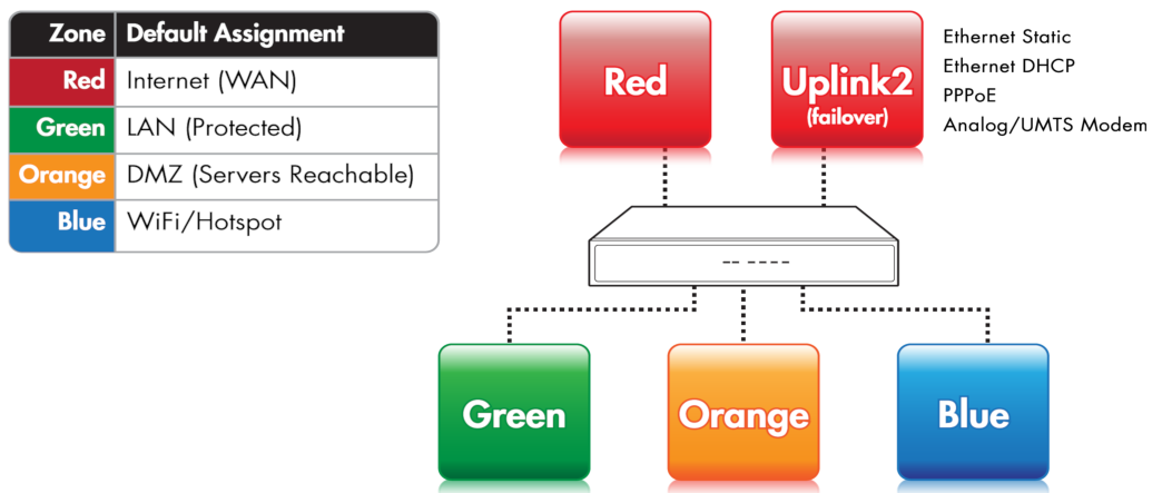
RED is the so-called Untrusted segment, i.e., the WAN: It encompasses all the networks outside the Connect Switchboard or, broadly speaking, the Internet, and is the source of incoming connections. This is the only zone that can not be managed: but only access to and from it can be granted or limited.
GREEN, the internal network, i.e., the LAN. This zone is the most protected one and is dedicated to the workstations and should never be directly accessed from the RED zone. It is also the only zone that by default can access the management interface.
ORANGE The DMZ. This zone should host the servers that need to access the Internet to provide services (e.g., SMTP/POP, SVN and HTTP and so on). It is a good practice that the ORANGE zone be the only zone directly accessable from the RED zone. Indeed, if an attacker manages to break into one of the servers, she will be trapped within the DMZ and will not be able reach the GREEN zone, making impossible for her to gain sensitive information from local machines in the GREEN zone.
BLUE, the WiFi zone, i.e., the zone that should be used by wireless clients to access the Internet. Wireless networks are often not secure, so the idea is to trap by default all the wireless connected clients into their own zone without access to any other zone except RED.
For the Connect Switchboard to correctly operate, it is not necessary to configure the ORANGE and BLUE zones. Indeed, it suffices to define the GREEN and RED zones to have a working appliance, unless the Network Mode is no uplink, in which the only mandatory zone is the GREEN.
The Connect Switchboard has pre-defined firewall rules that forbid the network
traffic to flow between some of the zones. Besides the four main
zones, the OpenVPN clients zone (sometimes called PURPLE) exists and
is used by the OpenVPN remote users that connect to the Connect Switchboard; by
default, the OpenVPN clients are bridged to the GREEN zone,
therefore the Purple zone coincides with the default green zone,
192.168.0.15/24.
To each zone corresponds an (network) interface and an IP address. The interface is the (ethernet or wireless) port through which the network traffic flows to the zone, so RED interface it the port through which you can reach the RED zone and the Internet. The IP address of the interface is the <Zone>IP. For example, the factory setting for the GREEN zone is the 192.168.0.15/24 network, hence the GREEN interface will have IP 192.168.0.15, which is referenced to as the GREENIP.
See also
- VPN
for a description of OpenVPN
EMI, The Endian Management Interface
EMI is the web interface used to access and configure all Connect Switchboard services, which has been designed to be easy to use, and consists of three main parts: The header, the menubar, and the main area. A sample screenshot of the System Dashboard can be seen below.
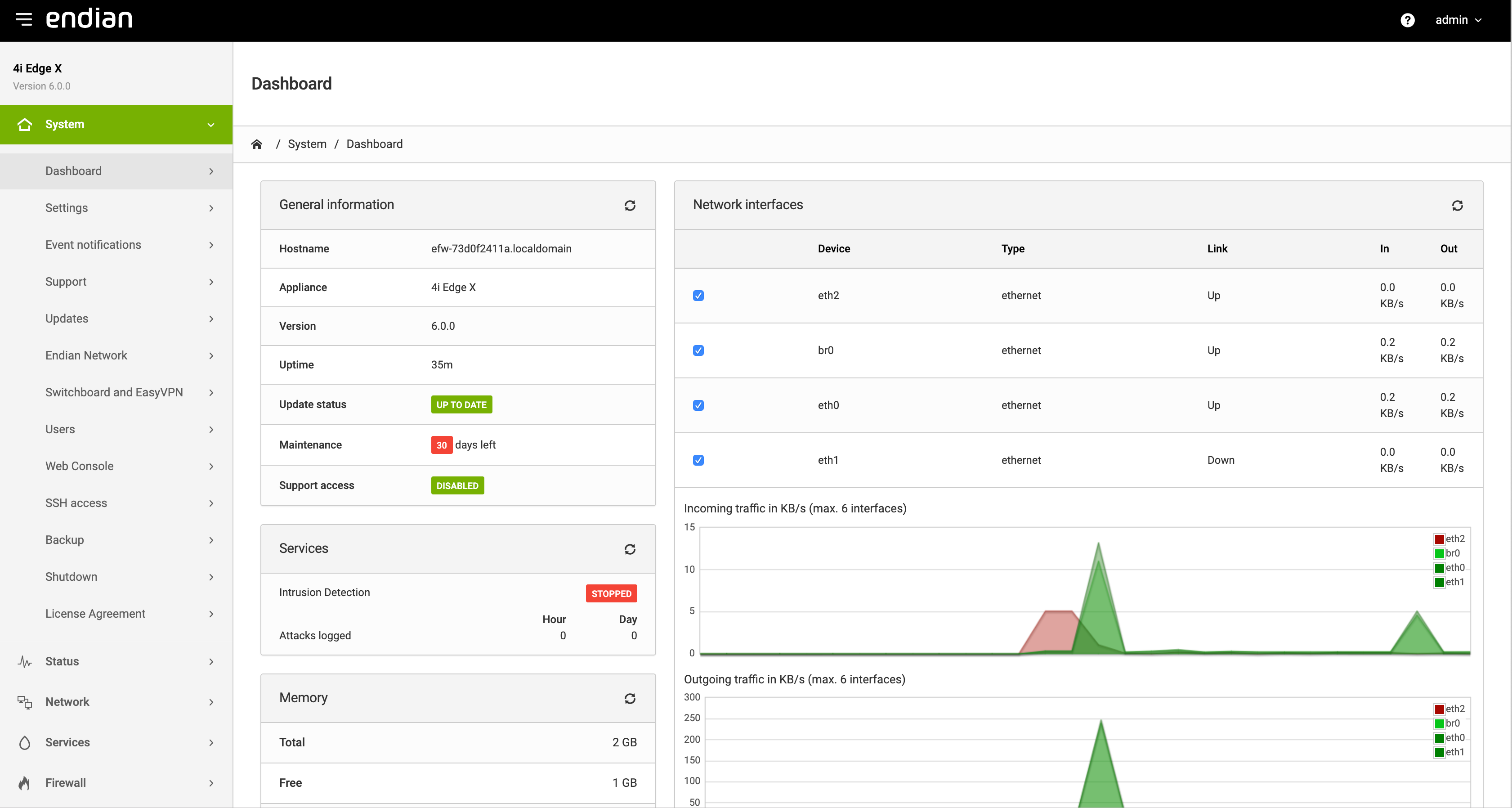
The Header

The header of the page contains a button to toggle the navigation menu and the Endian logo on the left, while on the right-hand side two links appear: one to the online documentation (the help icon), which is context-dependent (i.e., from each page the correspondent help will be displayed) and one to logout from the GUI, which shows also the name of the currently logged in user. This part is static and does not change.
The Menubar
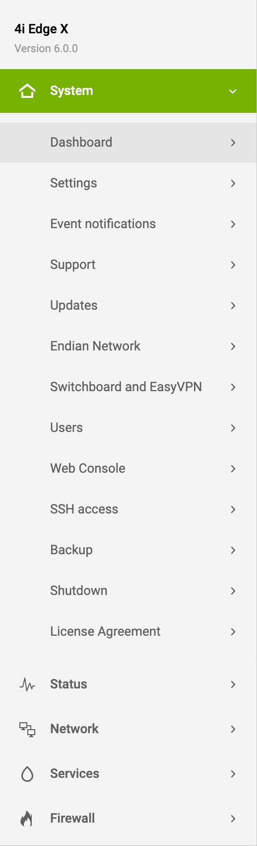
The menubar is located on the left-hand side of the web interface. When clicking on one of the modules (e.g., Services), its background becomes green, to emphasise the current open module and the items contained in the module appear. When clicking on a menu item, the title of the browser’s window title and the main area title change, since they are context-dependant, and carry the current item’s name. By default, the GUI opens on the item.
The Main Area
The main area contains all the information and settings encompassed by the current selection of the menu item. On top of the area, the current location of the page is shown (i.e., System / Dashboard)
Some of the pages (like e.g., the Dashboard or parts of the Service, Status, and Logs modules) are simply informative, showing the current status of the Connect Switchboard either graphically or textually. In the latter case, the output of Linux commands is used and shown on the screen.
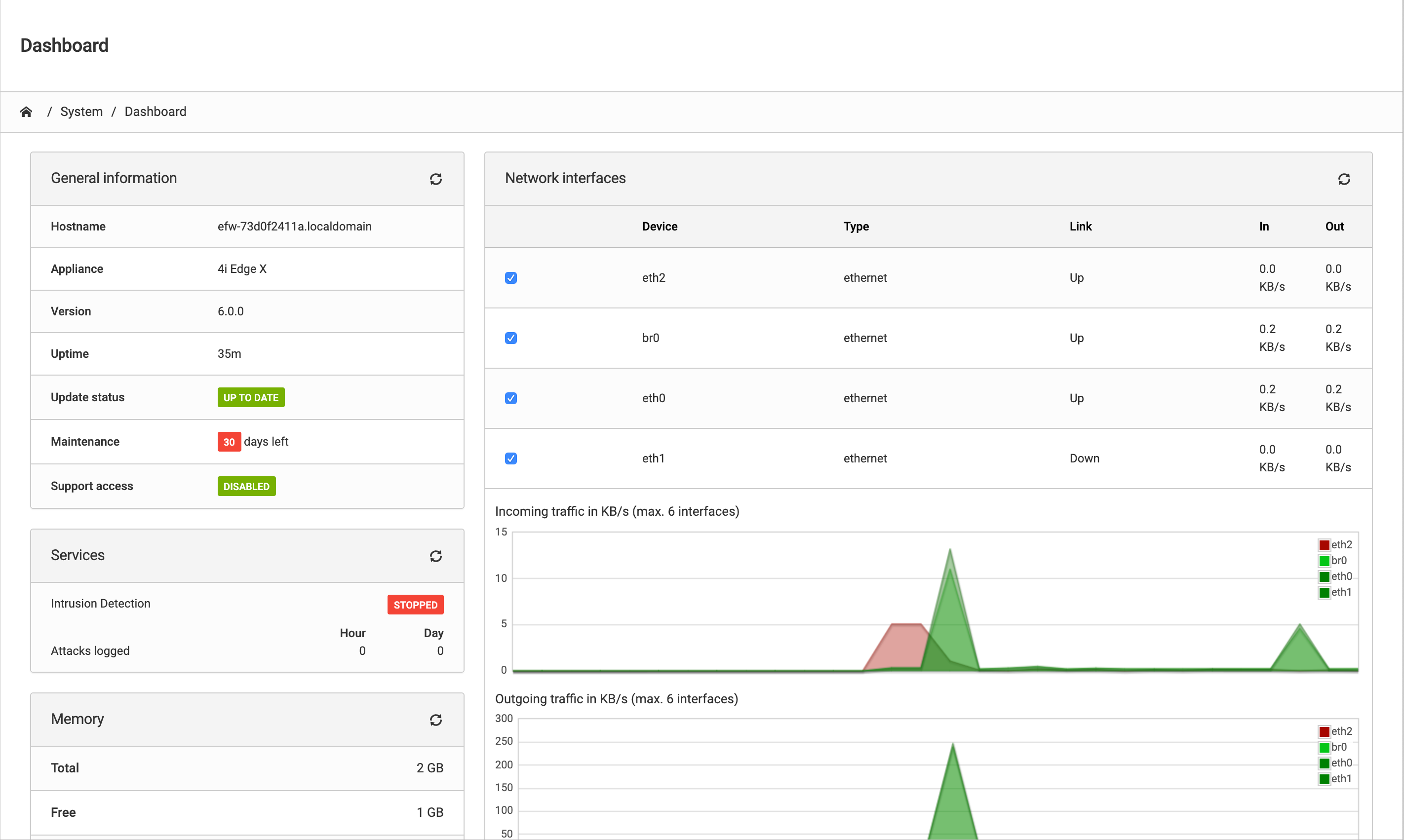
The vast majority of the pages, however, shows a table containing various information about the current configured settings, allowing to modify or delete existing items and settings and to add new ones. Particularly elaborate services like e.g., the OpenVPN infrastructure or the firewall, contain so many configuration options that a single page does not suffice to present them all, so the available settings are grouped together and organised using tabs and expandable boxes, possibly split across multiple pages. additional pages.
Accessing the Connect Switchboard
There are several ways to access the Connect Switchboard: The most intuitive and straightforward one is from the web-based GUI, EMI. A console-based access, via SSH and serial port is also possible, although they are suggested to advanced users only.
The Connect Switchboard GUI
Hint
The default IP address of the Connect Switchboard is 192.168.0.15.
The recommended access to the Connect Switchboard GUI is very simple: Start the browser and enter the GREENIP address, whether or not this is the first time the Connect Switchboard is used.
The browser will be redirected to a secure HTTPS connection on port 10443. Since Connect Switchboard uses a self-signed HTTPS certificate, the browser might ask to accept the certificate during the first connection. The system will then ask for username and password. Specify “admin” as the username and provide the password received from the reseller or, if the Connect Switchboard has already been customised, insert the password that provided during the installation.
After entering the password, the Dashboard of the Connect Switchboard GUI is displayed, and it is possible to immediately start exploring the information available on this interface or further browse and configure the appliance. The rest of this manual follows the layout of the main navigation bar: Each item in the main menu-bar represents a different section of the Connect Switchboard and is presented in a separate chapter, with sub-menu items and tabs having sub- and sub-sub-sections headings markup respectively.
Console-based access
Console-based access to the Connect Switchboard is suggested only to users that are acquainted with the Linux command line.
Two possibilities are available to reach the CLI: Using SSH access or via serial console. SSH access is by default disabled, but can be activated under , while Serial Console access is enabled by default on all appliances with the following parameters:
port: ttyS0
bit, parity bit, stop bit: 8, N, 1
speed: 115200 baud
The connection using the serial console requires:
A suitable terminal program like minicom for Unix/Linux boxes or putty for MS Windows.
A workstation with a serial interface
A nullmodem cable to connect a workstation to the appliance
or
Terminal program.
Networked Serial-to-Ethernet adapter.
Serial-to-Ethernet cable to connect the appliance to the adapter.
Note
In case the network is not configured properly, the serial console may represent the only way to access the Connect Switchboard.