
This sections presents the conventions used in the remainder of the manual, then provides introductory notions about the concept of zones, and finally describes the GUI of the Endian UTM 5.1 products and the possible ways to access the Endian UTM Appliance.
This manual has been written for the 5.1 release and is intended for all types of the Endian UTM Appliance series. Since the functionalities and abilities may differ between the various Endian UTM Appliances, the description of some of the displayed data or configuration options may slightly vary for some appliance or not being present at all. This guide is intended both as an online, contextual help as well as an user manual, providing also quick introductory descriptions to some of the concepts that lay behind the various functionalities provided by the Endian UTM Appliance.
Feedback about this guide, or any error found, can be reported using the Endian's bug tracker at https://jira.endian.com/ using the Documentation component.
The remainder of this section contains some basic information about this guide and how to move the first steps within the Endian UTM Appliance, introducing some important concepts and describing the most significant parts of GUI.
To improve the readability and clarity of this document, several conventions are used:
A Tooltip is displayed for various terms when moving the mouse over them.
A Button shows a clickable part of the GUI that is used to Save the current settings or to open a pop-up menu to upload a file on the Endian UTM Appliance. Note that the same button may be rendered differently on different browsers. For example, the button Browse… on Firefox-based browsers becomes Choose File… on Chrome-based browsers.
F5 or Ctrl+F5 show respectively, a keyboard shortcut or a combination of keys to be pressed together.
A (hyper)link is a clickable item of the GUI that will open a new page when clicked.
Besides for emphasis, italics is used to denote non-interactive objects or labels within the web GUI, while underlined word(s) and indicate objects that require user interaction, i.e., to open a hyperlink to open a new page or to click on a button to carry out some action.
Admonitions are employed to mark items, actions, or tasks that require special attention:
Warning
Changing this value will cause the service to restart!
Note
Remember that this option can be modify this later.
Hint
Tips about configuration of options
A relevant subject or an example
In boxes like this one (“topic”), there are explanation of some subject that requires a not-so-short description and is relevant to the topic of the section or to the configuration of some setting. Also, quick how-tos or examples may appear in it. At their bottom there might be present one or more hyperlinks to online resources.
Functionalities that have been added, modified, or removed, as well as changes in the GUI layout in the latest version are explicitly tagged:
New in version 5.0: Feature that has first appeared in 5.0, and a and short description.
Changed in version 5.0: Feature that was present in previous releases, but that changed in the 5.0, or feature that was removed in that version.
A sequence like requires to click on each of the items, in the sequence shown, to reach a particular page or configuration item. This example shows how to reach the page that shows the configuration of the system rules for the firewall’s DNAT.
Alternatively, in a sequence like , the […] means that there is a large number of objects (in this case there is a list of firewall’s rules) from which one should be chosen to carry out on it the action (Edit).
These sequences can be found within See also boxes, underheath an hyperlink, like this one:
See also
In the box, the hyperlink gives direct access to the documentation, while the sequence underneath it shows how to reach from the home page, the page where to configure that functionality.
Often, a See also box is used to provide links to resources like e.g., online how-tos or other parts of the documentation.
There are also some terms that have a special usage or meaning throughout this manual, and that can be found in the Glossary.
One of the most important concepts on which the Endian UTM Appliance is grounded, the Zone, finds its root in IPCOP’s idea to protect the networks it can reach by grouping them into different segments -the zone, indeed- and allowing the traffic to be exchanged only in certain directions among these segments. The four main zones are identified by a color and may group together a number of servers of workstation that have a same purpose.
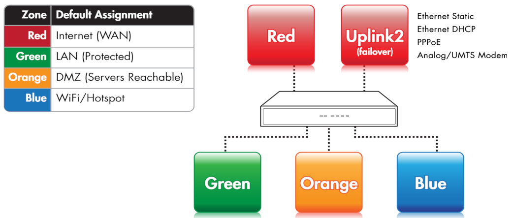
RED, this is the so-called Untrusted segment, i.e., the WAN: It encompasses all the networks outside the Endian UTM Appliance or, broadly speaking, the Internet, and is the source of incoming connections. This is the only zone that can not be managed: but only access to and from it can be granted or limited.
GREEN, the internal network, i.e., the LAN. This zone is the most protected one and is dedicated to the workstations and should never be directly accessed from the RED zone. It is also the only zone that by default can access the management interface.
ORANGE, The DMZ. This zone should host the servers that need to access the Internet to provide services (e.g., SMTP/POP, SVN and HTTP and so on). It is a good practice that the ORANGE zone be the only zone directly accessible from the RED zone. Indeed, if an attacker manages to break into one of the servers, she will be trapped within the DMZ and will not be able reach the GREEN zone, making impossible for her to gain sensitive information from local machines in the GREEN zone.
BLUE, the WiFi zone, i.e., the zone that should be used by wireless clients to access the Internet. Wireless networks are often not secure, so the idea is to trap by default all the wireless connected clients into their own zone without access to any other zone except RED.
For the Endian UTM Appliance to correctly operate, it is not necessary to configure the ORANGE and BLUE zones. Indeed, it suffices to define the GREEN zone, since also the RED zone can be in some cases left unconfigured.
The Endian UTM Appliance has pre-defined firewall rules that forbid the network traffic to flow between some of the zones. Besides the four main zones, two more zones are available, but are used only in advanced setups: The OpenVPN clients zone (sometimes called PURPLE), and the HA zone. These are two special zones that are used as networks for the OpenVPN remote users that should connect to the Endian UTM Appliance and for the HA service. By default they use the 192.168.15.0/24 and 192.168.177.0/24 (in CIDR notation, see below) networks respctively, so those networks ranges should not be used in the main zones, especially when planning to use either of these services. Indeed, those networks would overlap, possibly causing undesirable effects. The IP ranges of these two zones can however be modified during the set up of the OpenVPN or HA services.
In any case, the IP range used for the OpenVPN clients should never overlap the IP range of other services (like e.g., the DHCP server), because this may cause undesirable effects.
In the default setup, to each zone corresponds an (network) interface (or NIC), a subnet, and to each NIC corresponds one IP address. The interface is the (ethernet or wireless) port through which the network traffic flows to the zone, so RED interface is the port through which the RED zone and the Internet are reachable. The IP address of the interface is the <Zone> IP. For example, in its factory setting, the GREEN zone is assigned the 192.168.0.15/24 network, hence the GREEN interface will have IP 192.168.0.15, which is usually referenced to as the GREENIP.
IPv4 and CIDR notation.
An IPv4 address is a network address whose length is 32 bits, divided in four, 8-bits long octets. In decimal, each octet can assume any value between 0 and 255 (28= 256).
When specifying a network range, the IP address of the first host on the network along with the subnet mask, or netmask for short, is given, which defines the number of hosts available in that network. The subnet is defined as the length of the network prefix, i.e., that part of the address shared by all the hosts in a network.
There are two possibilities to denote the network/netmask pair:
explicitly, i.e., both are given in quad dotted notation. For example:
network 192.168.0.0
netmask 255.255.255.0
This is a network starting at the address 192.168.0.0 with 256 host available, i.e., the network range from 192.168.0.0 to 192.168.0.255. The first three octet in the netmask are 255, showing that there are no free host (or that this part of the address is the network prefix), while the fourth is 0, meaning that all hosts (256 - 0 = 0) are available.
in CIDR notation, a more compact way to show the network range, in which the free bits instead of the free hosts are given. The same network range as above is expressed as:
192.168.0.0/24
This notation shows the length in bits of the shared part of the IP address. 24 means that the first three octets (each consisting of 8 bits) are shared, while the fourth octet is free, giving a number of free hosts that is equivalent to 32 - 24 = 8 bits, i.e., 256 hosts.
The same line of reasoning can apply to an IPv6 address, with the only difference that IPv6 addresses are 128 bits long.
See also
for a description of High Availability
for a description of OpenVPN
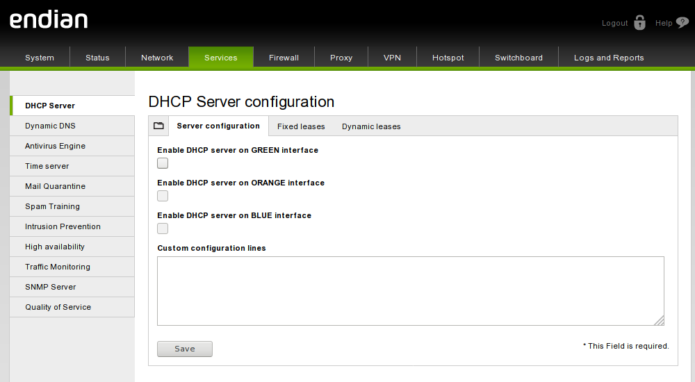
EMI is the GUI of the Endian UTM Appliance, the web interface used to access and configure all Endian UTM Appliance services. It is the same for all the Endian products and consists of five main parts: The header, the main menubar, the sub-menu, the main area, and the footer. A sample screenshot of the Services module can be seen below.

The header of the page contains the Endian logo and the product’s name and version on the left-hand side, while on the right-hand side there is an image showing two links accompanied by an icon appear: One to logout from the GUI, and one to the online documentation (help), which is context-dependent (i.e., from each page the correspondent help will be displayed). This part is static and does not change.
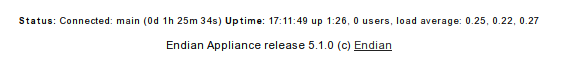
The footer is placed at the very bottom of the page and consists of two lines of text with a few infomation on the running Endian UTM Appliance. The top line shows (Status:) whether an uplink is connected or connecting and which one (if there are more than one uplinks defined) and the time elapsed (Uptime:) since the last time the connection was established and the uptime of the machine, which is reported as the output of the uptime command, i.e., the time since last boot, the number of users and the load average. By changing page, the information is updated. The bottom line shows the version of the appliance with the deployset, and the copyright, with a link to Endian web site.

The main navigation bar, situated right below the header, is a menu bar with a black background and a green bottom line that displays all the available sections of the Endian UTM Appliance. When clicking on one of the modules (e.g., Services), its background becomes green, to emphasise the current open module. Upon clicking on a menu item, the sub-menu on the left of the page and the title at the top of the main area change, since they are context-dependant. By default, the GUI opens on the System menu.

The sub-menu appears on the left-hand side of the GUI and changes depending on the module selected on the menubar. It appears as a vertical list of items that can be clicked to change the content of the main area and to access all the functionalities included in that Endian UTM Appliance‘s module.
The main area contains all the information and settings encompassed by the current selection of the menu/sub-menu combination. Some of the pages (e.g., the Dashboard or parts of the Service and Logs modules) are simply informative, showing the current status of the Endian UTM Appliance either graphically or textually, in the latter case conveying the output of linux commands on the screen. The vast majority of the pages, however, shows a table containing various information about the current configured settings, allowing to modify or delete existing items and settings and to add new ones. Particularly elaborate services like e.g., the HTTP proxy or the firewall, contain so many configuration options that a single page does not suffice to present them all, so the available settings are grouped together and organised in tabs.

Within tabs, often the configuration options are packed in one or more boxes, that gather together settings that refer to a common part of the overall configuration.
The only exception to the layout of the Endian UTM Appliance GUI is the Hotspot Administration Interface, pictured in the screenshot below, which has no footer, places the submenu under the main menubar, and presents on the far right of the menubar a Main menu link to go back to the main menu.
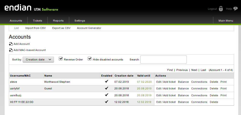
Note that when referring to items under the Hotspot Administration Interface, the initial Menubar is usually omitted.
There are several ways to access the Endian UTM Appliance: The most intuitive and straightforward one is from the web-based GUI, EMI. A console-based access, via SSH and serial port is also possible, although they are suggested to advanced users only.
Hint
The default IP address of the Endian UTM Appliance is 192.168.0.15.
The recommended access to the Endian UTM Appliance GUI is very simple: Start the browser and enter the GREENIP address, whether or not this is the first time the Endian UTM Appliance is used.
The browser will be redirected to a secure HTTPS connection on port 10443. Since Endian UTM Appliance uses a self-signed HTTPS certificate, the browser might ask to accept the certificate during the first connection. The system will then ask for username and password. Specify admin as the username and provide the password received from the reseller or, if the Endian UTM Appliance has already been accessed, insert the password provided during the installation.
After entering the password, the Dashboard of the Endian UTM Appliance GUI is displayed, and it is possible to immediately start exploring the information available on this interface or further browse and configure the appliance. The rest of this manual follows the layout of the main navigation bar: Each item in the main menu-bar represents a different section of the Endian UTM Appliance and is presented in a separate chapter, with sub-menu items and tabs having sub- and sub-sub-sections headings markup respectively.
Console-based access to the Endian UTM Appliance is suggested only to users that are acquainted with the Linux command line.
Two possibilities are available to reach the CLI: Using SSH access or via serial console. SSH access is by default disabled, but can be activated under , while Serial Console access is enabled by default on all appliances with the following parameters:
port: ttyS0
bit, parity bit, stop bit: 8, N, 1
speed: 115200 baud
Note
The baud rate is 38400 in older appliances (previous to 3.0 release).
The connection using the serial console requires:
A suitable terminal program like minicom for Unix/Linux boxes or putty for MS Windows.
A workstation with a serial interface
A nullmodem cable to connect a workstation to the appliance
or
Terminal program.
Networked Serial-to-Ethernet adapter.
Serial-to-Ethernet cable to connect the appliance to the adapter.
Note
In case the network is not configured properly, the serial console may represent the only way to access the Endian UTM Appliance.